

Flyback converter
A converter and flyback technology, applied in the field of power conversion, can solve problems such as low conversion efficiency and high switching loss, and achieve the effect of high conversion efficiency and low switching loss
- Summary
- Abstract
- Description
- Claims
- Application Information
AI Technical Summary
Problems solved by technology
Method used
Image

Examples
Embodiment Construction
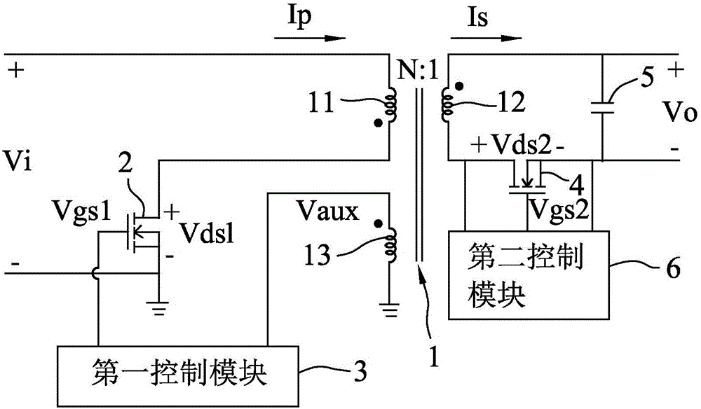
[0038] refer to Figure 1 to Figure 3 , an embodiment of the flyback converter of the present invention is suitable for converting an input voltage Vi into an output voltage Vo, and the flyback converter includes a transformer 1, a first switch 2, a first control module 3 , a second switch 4 , an output capacitor 5 and a second control module 6 .
[0039] The transformer 1 includes a primary winding 11 , a secondary winding 12 and an auxiliary winding 13 . Each of the primary, secondary and auxiliary windings 11, 12, 13 has a first end (eg, figure 1 a dotted end with a black dot shown) and a second end (e.g., figure 1 shown a non-dotted end without a black dot). The first ends of the primary, secondary and auxiliary windings 11, 12, 13 have the same voltage polarity. The number of turns of the primary winding 11 is N times that of the secondary winding 12 (that is, a turns ratio of the primary winding 11 and the secondary winding 12 is N), and the primary winding 11 receiv...
PUM
 Abstract
Description
Claims
Application Information