
System message transmission method and device

A technology of system message and transmission method, which is applied in the field of system message transmission method and device, and can solve problems such as resource occupation and lack of solutions

Active Publication Date: 2017-03-08
ZTE CORP
View PDF7 Cites 9 Cited by
  • Summary
  • Abstract
  • Description
  • Claims
  • Application Information

AI Technical Summary

Problems solved by technology

Considering that the transmission bandwidth and downlink subcarrier spacing of NB-LTE are the same as the bandwidth and subcarrier spacing of a PRB in the LTE system, NB-LTE may also coexist in the same spectrum as the LTE system, for example, in a system with a system bandwidth of 20MHz In the LTE system, a 180kHz bandwidth is allocated for the transmission of NB-LTE system signals, but since some resources of the LTE system have been pre-occupied, in order to ensure that the NB-LTE system and LTE system signals are not transmitted on the same resource, two The mutual interference of the system still lacks an effective solution

Method used


Image

  • System message transmission method and device
  • System message transmission method and device
  • System message transmission method and device

Examples


Embodiment 1

[0176] The initial OFDM symbol information includes two or four states;

[0177] It specifically includes: 1 bit indicates the available resource information of the physical downlink channel.

[0178] Two resource mapping modes are predefined, indicated by 1-bit signaling, and the available resource information of the physical downlink channel is indicated according to the signaling:

[0179] For example: the first mapping mode includes: the physical downlink channel is mapped from the first OFDM symbol of the subframe, and / or the corresponding available resource unit is the remaining resources after dividing the dedicated reference signal of the fixed single-port virtual cell; the second mapping mode Including: the physical downlink channel is mapped from the fourth OFDM symbol of the subframe, and / or, the corresponding available resource unit is the remaining resource after dividing the dedicated reference signal of the fixed four-port virtual cell;

[0180] or,

[0181] T...

Embodiment 2

[0187] Since the CRS on the LTE system MBSFN (Multimedia Broadcast multicast service Single Frequency Network, multicast / multicast single frequency network) subframe is only located in the first two OFDM symbols, the PBCH needs to be demodulated through the CRS and / or synchronization channel, so the PBCH is located in the non- On MBSFN subframes (0, 4, 5, 9);

[0188] If the synchronization signal is located on the MBSFN subframe, the influence of the CRS of the LTE system on the synchronization signal can be avoided, but this will cause restrictions on the transmission of multicast services. , 7, 8) and the synchronization signal is not located on the MBSFN subframe (0, 4, 5, 9) two scenarios provide the PBCH mapping scheme, specifically as shown above;

[0189] It should be noted that: the above description shows that the physical broadcast channel is located in different adjacent subframes of the synchronization channel, but it does not limit that there must be a physical b...

Embodiment 3

[0194] The NB-LTE frequency domain position information is mainly used for CRS sequence generation; wherein, the CRS sequence follows the LTE system CRS sequence generation method, therefore, it is necessary to determine the frequency domain position corresponding to NB-LTE in order to generate the CRS sequence;

[0195] The configuration information related to the physical shared channel carrying system information includes at least one of the following: the number of bits of system information carried by the physical shared channel, the number of subframes occupied by the physical shared channel, and the radio frame occupied by the physical shared channel information;

[0196] The terminal access configuration information specifically includes: whether to allow terminal access, and / or, system status information, and / or terminal uplink access resource configuration information;

[0197] The terminal determines whether to access the system and / or how to access the system accordi...


PUM


Abstract

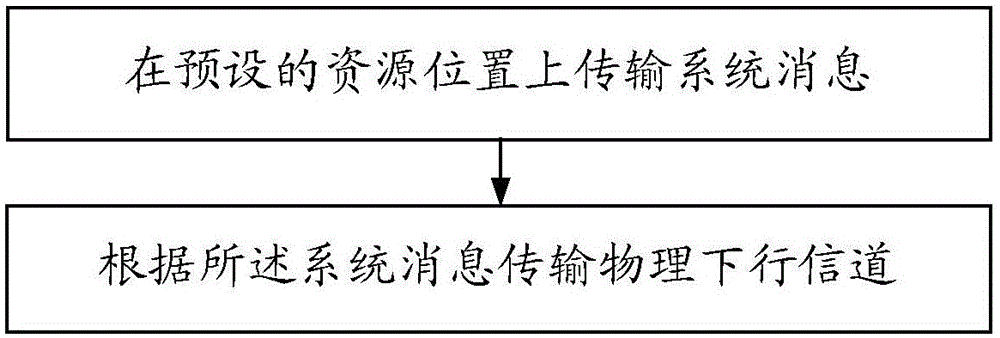
The invention provides a system message transmission method and device and relates to the field of wireless communication. The method comprises the steps of transmitting system messages at a preset resource position; transmitting a physical downlink channel according to the system messages, wherein the system messages comprise at least one of position information of a frequency domain at which a system is located, configuration information of the physical downlink channel bearing the system messages, configuration information of terminal access, available resource information of the physical downlink channel and wireless frame information. Through application of the predefined transmission and signal indication combined method, the mutual interference among signals can be reduced during different system spectrum sharing, the condition that different systems carry out different signal transmission on the same resource is reduced, the comprehending consistency between the systems and the terminal is ensured, and the data transmission performance is improved.

Description

technical field [0001] The invention relates to the field of wireless communication, in particular to a system message transmission method and device. Background technique [0002] Machine Type Communication (MTC for short) User Equipment (User Equipment or Terminal for short), also known as Machine to Machine (M2M) user communication equipment, is currently the main application form of the Internet of Things. In the 3GPP (3rd Generation Partnership Project, Third Generation Partnership Project) technical report TR45.820V200, several technologies applicable to cellular-level Internet of Things (C-IOT, Internet Of Things) are disclosed, among which, NB-LTE (Narrowband Long Term Evolution, narrowband long-term evolution) technology is the most eye-catching. The system bandwidth of the system is 200kHz, which is the same as the channel bandwidth of GSM (Global System for Mobile Communication, Global System for Mobile Communication), which brings great convenience for the NB-LT...

Claims


Application Information

Patent Timeline
Patent Type & Authority Applications(China)
IPC IPC(8): H04W28/08H04W72/12
CPCH04W28/08H04W72/52H04L5/0048H04L5/0053H04L5/0073H04W48/10H04L5/005H04L5/0007H04J11/0066H04W72/30H04W72/541
Inventor 戴博夏树强郁光辉胡留军袁弋非
Owner ZTE CORP
Learn More