Dust-extraction device special for electric control cabinet

A technology for power control cabinets and dust removal devices, applied in the direction of dust removal, cleaning methods and tools, cleaning methods using tools, etc., can solve problems such as economic losses, inability to unload at will, and affect the service life of equipment to ensure safety , Improve efficiency and adapt to the effect of surface

Inactive Publication Date: 2017-03-15
STATE GRID SHANDONG ELECTRIC POWER CO LONGKOU POWER SUPPLY CO
View PDF6 Cites 10 Cited by
  • Summary
  • Abstract
  • Description
  • Claims
  • Application Information

AI Technical Summary

Problems solved by technology

[0002] In the secondary equipment of the power system, a large number of electronic equipment requires long-term unstoppable operation. With the operation of the equipment, a large amount of dust accumulates on the appearance of the equipment. After a long time, a layer of dust covers the surface of the equipment, which affects the heat dissipation of the electronic equipment and seriously affects the service life of the equipment. At the same time, it is easy to cause electrostatic breakdown. However, when cleaning the dust regularly, because the equipment is fixed in the cabinet for a long time, it cannot be removed at will. At the same time, the gap between the devices is very small, usually only 4-5 cm, and the depth of the cabinet is nearly 100 cm. Left and right, it is difficult to insert cleaning tools such as rags and brushes into the gaps between the equipment, resulting in incomplete cleaning. Over time, dust accumulation will affect heat dissipation, and even static electricity will break down, which will cause the equipment to stop running, and it is also easy to cause personal injury or death due to electric shock. Not only will it cause economic losses, but it will also affect the stable operation of the power grid. Although the dust is small, it is extremely harmful. Therefore, the dust cleaning of electronic equipment has become a difficult problem in the daily maintenance of the computer room. , cannot effectively clean the upper surface, and cannot guarantee the safety of personnel and equipment when building a ladder

Method used


Image

  • Dust-extraction device special for electric control cabinet
  • Dust-extraction device special for electric control cabinet
  • Dust-extraction device special for electric control cabinet

Examples


Embodiment Construction

[0019] The following will clearly and completely describe the technical solutions in the embodiments of the present invention with reference to the accompanying drawings in the embodiments of the present invention. Obviously, the described embodiments are only some of the embodiments of the present invention, not all of them. Based on the embodiments of the present invention, all other embodiments obtained by persons of ordinary skill in the art without making creative efforts belong to the protection scope of the present invention.

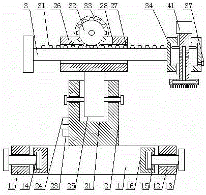
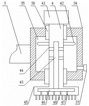
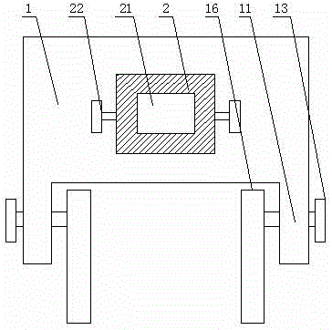
[0020] see Figure 1-4 , the present invention provides a technical solution: a special dust removal device for power control cabinets, including a base 1, the two ends of the front surface of the base 1 are provided with a clamping seat 11, and the inside of the clamping base 11 is provided with a clamping threaded hole 12, and the clamping The internal thread of the tight threaded hole 12 is connected with a clamping threaded rod 13, and the fr...


PUM


Abstract

The invention discloses a dust-extraction device special for an electric control cabinet. The dust-extraction device comprises a foundation, wherein an adjusting base is fixedly connected to the center of the upper surface of the foundation, an adjusting groove is formed in the inner part of the adjusting base, an adjusting rod is slidably connected to the inner part of the adjusting groove, a movable base is fixedly connected to the upper surface of the adjusting rod, a movable groove is formed in the inner part of the movable base, a movable rod is slidably connected to the inner part of the movable groove, a sweeping base is fixedly connected to the surface of a rear end of the movable rod, a cleaning hole is formed in the outer surface of the sweeping base, a cavity is formed in the inner part of the sweeping base, bearing pedestals are fixedly arranged on both the upper surface and the lower surface of the cavity, and a sweeping head is fixedly connected to the lower surface of a rotating shaft. According to the dust-extraction device special for the electric control cabinet, the foundation can be fixed on the electric control cabinet through clamping blocks connected by threads, not only efficiency and an adaptive surface of cleaning can be greatly improved, but also safety can be effectively guaranteed.

Description

technical field [0001] The invention relates to the technical field of cleaning devices, in particular to a special dust removal device for electric control cabinets. Background technique [0002] In the secondary equipment of the power system, a large number of electronic equipment requires long-term unstoppable operation. With the operation of the equipment, a large amount of dust accumulates on the appearance of the equipment. After a long time, a layer of dust covers the surface of the equipment, which affects the heat dissipation of the electronic equipment and seriously affects the service life of the equipment. At the same time, it is easy to cause electrostatic breakdown. However, when cleaning the dust regularly, because the equipment is fixed in the cabinet for a long time, it cannot be removed at will. At the same time, the gap between the devices is very small, usually only 4-5 cm, and the depth of the cabinet is nearly 100 cm. Left and right, it is difficult to ...

Claims


Application Information

Patent Timeline
Patent Type & Authority Applications(China)
IPC IPC(8): B08B1/04B08B15/04
CPCB08B1/002B08B1/04B08B15/04
Inventor 刘霞徐广林牛聪文黄婉思邹翔李敏于涵姚歆韩天麒张丽李志宏刘延馨徐培华
Owner STATE GRID SHANDONG ELECTRIC POWER CO LONGKOU POWER SUPPLY CO
Why Eureka
Try Eureka