Disintegrating slag afterheat utilizing system

A technology of waste heat and slag, applied in the direction of improving process efficiency, etc., can solve the problems of ineffective use of heat, many impurities in slag water, and inability to recycle slag water, etc., to achieve protection from corrosion and uniform heat transfer effect , long service life effect

Active Publication Date: 2013-06-05
JIGANG INT ENG & TECH CO LTD
View PDF5 Cites 10 Cited by
  • Summary
  • Abstract
  • Description
  • Claims
  • Application Information

AI Technical Summary

Problems solved by technology

[0002] Converter steel slag slag produces a large amount of hot water. Since the slag water has many impurities and is easy to scale, conventional waste heat recovery equipment cannot recover the waste heat of the slag water. Therefore, the heat in the hot water of steelmaking slag has long been It has not been effectively utilized. The curre

Method used


Image

  • Disintegrating slag afterheat utilizing system
  • Disintegrating slag afterheat utilizing system
  • Disintegrating slag afterheat utilizing system

Examples


Example Embodiment

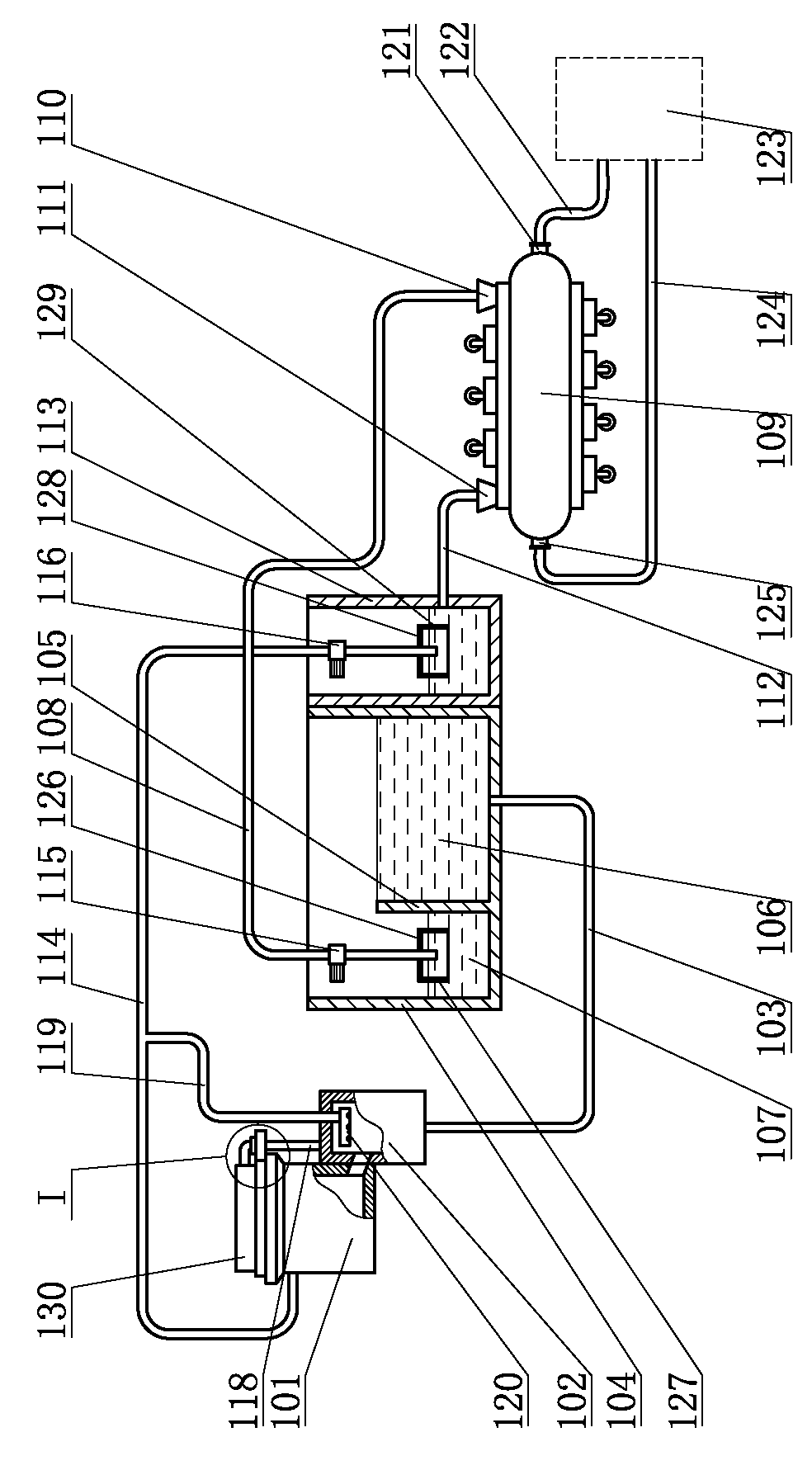
[0011] The slag waste heat utilization system of the present invention includes a slag slag tank 101, a slag discharge port at the bottom of the slag tank 101 is connected to the slag flushing ditch 102, and the slag slag tank 101 is connected to the top of the slag flushing ditch 102 through a steam discharge pipe 118. The bottom of the slag ditch 102 is connected to the sedimentation tank 104 through a drainage pipe 103. The sedimentation tank 104 is provided with an overflow partition 105. The overflow partition 105 divides the lower part of the sedimentation tank 104 into a sedimentation chamber 106 and a water purification chamber 107. The drainage pipe 103 is located On the sedimentation chamber 106 side of the sedimentation tank 104, a hot water supply pipe 108 is provided in the water purification chamber 107, a hot water circulation pump 115 is installed on the hot water supply pipe 108, and one end of the hot water supply pipe 108 is located inside the water purificatio...


PUM


Abstract

The invention discloses a disintegrating slag afterheat utilizing system. The disintegrating slag afterheat utilizing system comprises a disintegrating slag tank, wherein a deslagging port at the bottom of the disintegrating slag tank is communicated with a slag sluice, the disintegrating slag tank is communicated with the top of the slag sluice through a steam discharge pipe, the slag sluice is communicated with a sedimentation tank, an overflow baffle plate is arranged in the sedimentation tank, a hot water supplying and feeding pipe is arranged in the sedimentation tank and is connected with a heating water heat exchange device which is communicated with a cold water pond, a cold water supplying and feeding pipe is arranged in the cold water pond and is connected with the disintegrating slag tank, a spraying branch pipe is arranged on the cold water supplying and feeding pipe and is connected with a spraying pipe in the slag sluice, and the heating water heat exchange device is connected with a heating unit. The disintegrating slag afterheat utilizing system has the advantages of being free of influence of impurities in disintegrating slag water, being capable of recycling heat in disintegrating slag water, being contributed to saving of energy sources, reducing the pollution of iron and steel enterprises to environments, and recycling heat for heating so that the heating expenses of enterprises are saved.

Description

technical field [0001] The invention relates to a kind of stuffy slag equipment for steelmaking, in particular to a stuffy slag waste heat utilization system. Background technique [0002] Converter steel slag slag produces a large amount of hot water. Since the slag water has many impurities and is easy to scale, conventional waste heat recovery equipment cannot recover the waste heat of the slag water. Therefore, the heat in the hot water of steelmaking slag has long been It has not been effectively utilized. The current heat treatment method for stuffy slag water is direct discharge, which not only causes a huge waste of heat sources, but also brings huge economic losses to enterprises, and seriously pollutes the environment, aggravates the greenhouse effect, and destroys the earth environment in which human beings live. , causing serious social hazards. Contents of the invention [0003] The purpose of the present invention is to provide a steel slag slag waste heat u...

Claims


Application Information

Patent Timeline
IPC IPC(8): C21B3/08
CPCC21B2400/024C21B2400/08Y02P10/20
Inventor 姜进强孙璐穆艳春陈树国张东力陈以豹润建刚曾静王培磊程志洪孔林叶书开战立刚
Owner JIGANG INT ENG & TECH CO LTD
Why Eureka
Try Eureka