Power-driven hydraulic straightener for ring lock scaffold

The technology of straightening machine and disc buckle is applied in the field of electric hydraulic straightening machine of disc buckle frame, which can solve the problems such as the inability to adjust the speed of the hydraulic cylinder, the inability to adjust the speed of the oil cylinder, the inconvenience of clamping the disc buckle frame, etc., and the appearance is beautiful. , the effect of convenient operation and simple device structure

Active Publication Date: 2017-03-15
CHINA NUCLEAR IND 24 CONSTR
View PDF7 Cites 1 Cited by
  • Summary
  • Abstract
  • Description
  • Claims
  • Application Information

AI Technical Summary

Problems solved by technology

[0003] The purpose of the present invention is to overcome the deficiencies of the prior art, to provide an electro-hydraulic straightening machine for the coil rack, to solve the problem that the hydraulic cylinder of the coil rack straightening machine cannot adjust the speed, and the coil rack straightening machine clamps the coil rack Inconvenient, inconvenient to straighten any bend of the buckle frame
This utility solves the problem that the speed of the oil cylinder cannot be adjusted, and reasonably adjusts the speed during the modulation process to make it meet the operating habits of employees and improve the modulation speed

Method used


Image

  • Power-driven hydraulic straightener for ring lock scaffold
  • Power-driven hydraulic straightener for ring lock scaffold
  • Power-driven hydraulic straightener for ring lock scaffold

Examples


Embodiment 1

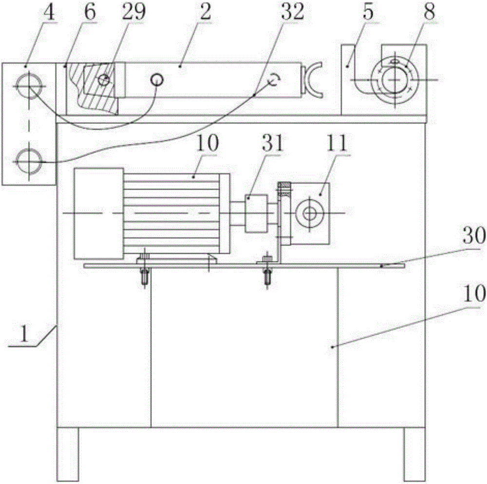
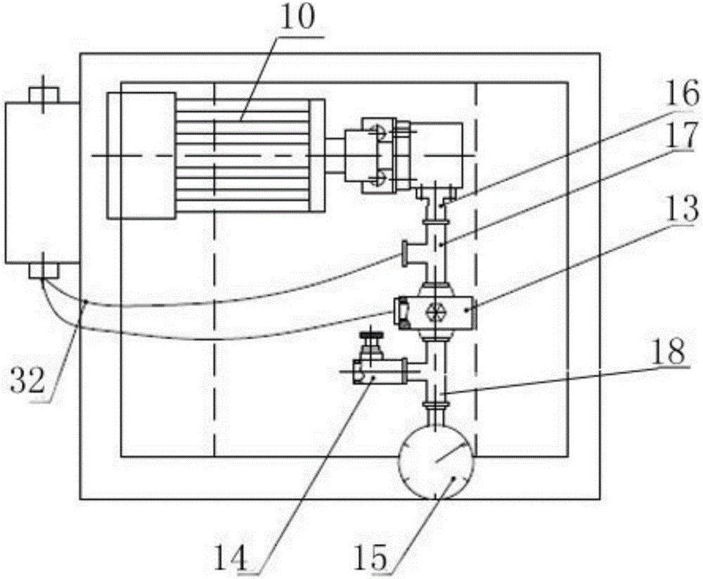
[0025] Such as Figure 1-2 As shown, an electro-hydraulic straightening machine for a coil frame of the present invention includes a straightening machine casing 1, a hydraulic cylinder 2, a hydraulic station 3, a steering valve 4, and a clamping platform 5 for a coil frame, and the coil frame 8 includes a support pipe 28 and disc buckle 25, generally a supporting pipe 28 is evenly welded with 2-4 disc buckles 25, and the straightening machine box body 1 adopts angle steel welding to form a frame type; a panel is placed on the frame, and an oil cylinder fixing plate is welded on the panel to fix the parts plate.

[0026] The hydraulic cylinder 2 is arranged on the upper side of the straightening machine casing 1 through the cylinder fixing assembly 6, the cylinder seat of the hydraulic cylinder 2 is installed on the cylinder fixing assembly 6 through the pin shaft 29, and the front end of the cylinder push rod 7 of the hydraulic cylinder 2 is provided with a useful For the st...

Embodiment 2

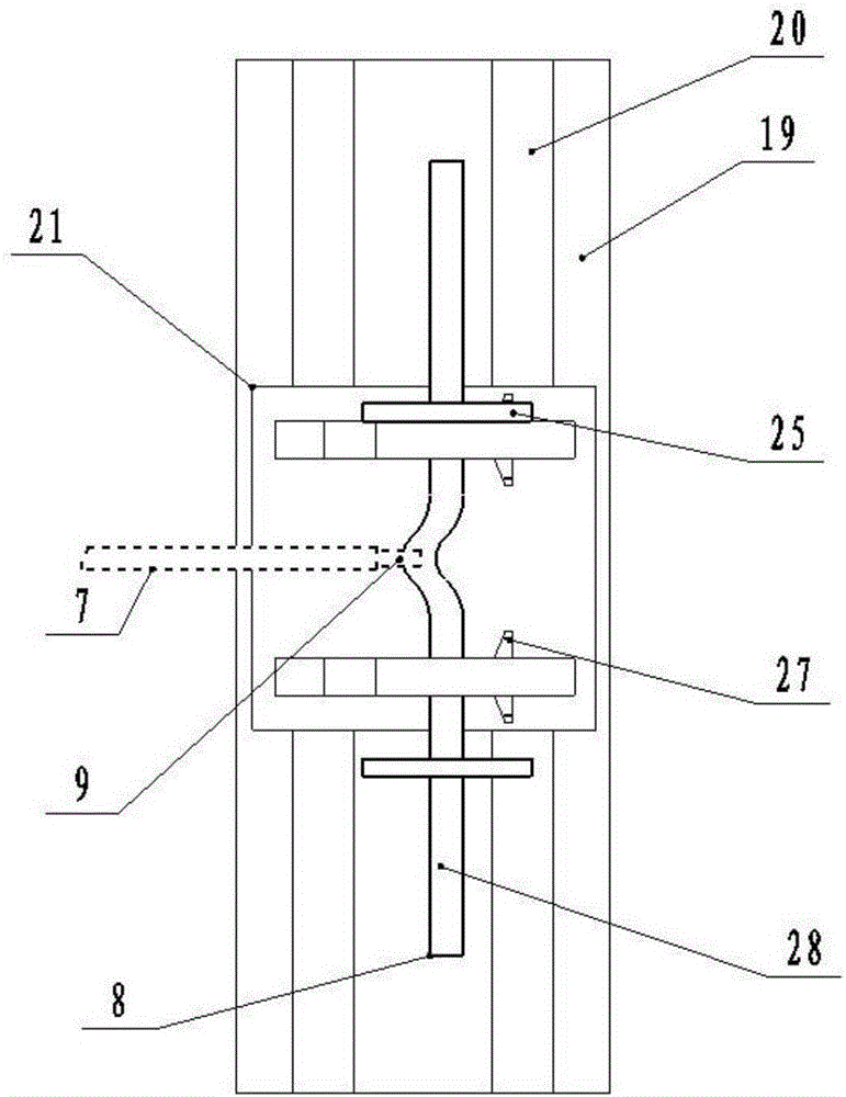
[0032] Such as Figure 3-4 As shown, the present invention is an electro-hydraulic straightening machine for coil racks. On the basis of Embodiment 1, the clamping table 5 for coil racks includes a fixed platform 19, a guide rail 20 and a moving frame for clamping the coil racks 8 21. The lower part of the fixed table 19 is fixed on the straightening machine box 1 by welding or bolts. The fixed table 19 is provided with two parallel guide rails 20. The guide rails 20 adopt an I-shaped shape, which is convenient for clamping the mobile frame 21 and the mobile frame. 21 is arranged on guide rail 19 and slides. The mobile frame 21 includes a chute platform 22 and a buckle frame clamping plate 23 for cooperating with the guide rail 19. The chute platform 22 is installed on the guide rail 19 to adjust and slide, and two parallel pan buckles are arranged on the chute platform 22. Frame clamping mounting plate 23, on which there is an L-shaped clamping slot 24 for clamping the disc ...


PUM


Abstract

The invention discloses a power-driven hydraulic straightener for a ring lock scaffold. The power-driven hydraulic straightener comprises a straightener box body, a hydraulic oil cylinder, a hydraulic station, a diversion valve and a ring lock scaffold clamping platform. The hydraulic oil cylinder is arranged on one side of the upper face of the straightener box body through an oil cylinder fixing assembly, a straightening pressing head used for straightening the ring lock scaffold is arranged at the front end of an oil cylinder push rod of the hydraulic oil cylinder, and the ring lock scaffold clamping platform is arranged on the other side, corresponding to the straightening pressing head, of the upper face of the straightener box body. The hydraulic station is arranged in the straightener box body and is connected with the hydraulic oil cylinder through the diversion valve. The power-driven hydraulic straightener solves the problem that the speed of the oil cylinder cannot be adjusted and other problems, the speed in the modulation process is reasonably adjusted to meet the operation habit of workers, and the modulation speed is increased. The power-driven hydraulic straightener is simple in structure, attractive in appearance, convenient to operate, flexible in application and the like. The power-driven hydraulic straightener can adjust the ring lock scaffold and can also adjust steel pipes with less bending and other parts needing to be straightened.

Description

technical field [0001] The invention relates to the field of a coil rack straightening machine, in particular to an electro-hydraulic straightening machine for a coil rack. Background technique [0002] There is no way to use a stick shaft type steel pipe straightening machine to straighten the buckle frame, and it needs to be straightened manually, but the efficiency of manual straightening is low. At present, there are problems in the domestic coil rack straightening machine: ①The hydraulic cylinder of the coil rack straightening machine cannot adjust the speed; ②The coil rack straightening machine mostly adopts vertical straightening, and the volume is large; It is inconvenient to install the buckle rack with the machine clamp, and it is not convenient to straighten any bend of the buckle rack. Contents of the invention [0003] The purpose of the present invention is to overcome the deficiencies of the prior art, to provide an electro-hydraulic straightening machine f...

Claims


Application Information

Patent Timeline
Patent Type & Authority Applications(China)
IPC IPC(8): B21D3/10
CPCB21D3/10
Inventor 牟中良刘畅李强钟涛方仁宝熊双燕朱德敏秦剑田延华张军高进仓胡光辉
Owner CHINA NUCLEAR IND 24 CONSTR
Why Eureka
Try Eureka