A Torque Mechanism Used in the Production of Crankshaft Connecting Rod

A crankshaft connecting rod and connecting rod technology, which is applied in the field of pneumatic torque devices, can solve problems such as high labor intensity, worker injury, and occupational diseases, and achieve the effect of improving operation convenience, easy and labor-saving operation, and reducing labor intensity

Active Publication Date: 2019-02-19
重庆昌跃机电制造有限公司
View PDF14 Cites 0 Cited by
  • Summary
  • Abstract
  • Description
  • Claims
  • Application Information

AI Technical Summary

Problems solved by technology

In the prior art, workers need to manually assemble the connecting rod cover and connecting rod. First, the connecting rod cover and connecting rod bolts are pre-screwed onto the big head, and then the connecting rod is held in one hand, and the other is held with a torque gun to tighten the connecting rod bolts. The disadvantage is that because the connecting rod needs to be fixed by hand, it is more laborious to tighten, so that the labor intensity of the workers is high, which not only makes the assembly efficiency low, but also easily injures the workers due to misoperation; at the same time, because the torque gun has a certain weight, Workers need to hold the torque gun for a long time and maintain a fixed posture. The joints of the workers are easily damaged and cause occupational diseases, and they are also prone to fatigue, which leads to safety accidents.

Method used


Image

  • A Torque Mechanism Used in the Production of Crankshaft Connecting Rod
  • A Torque Mechanism Used in the Production of Crankshaft Connecting Rod
  • A Torque Mechanism Used in the Production of Crankshaft Connecting Rod

Examples


Embodiment Construction

[0016] The technical solutions in the present invention will be further described below in conjunction with the accompanying drawings and embodiments.

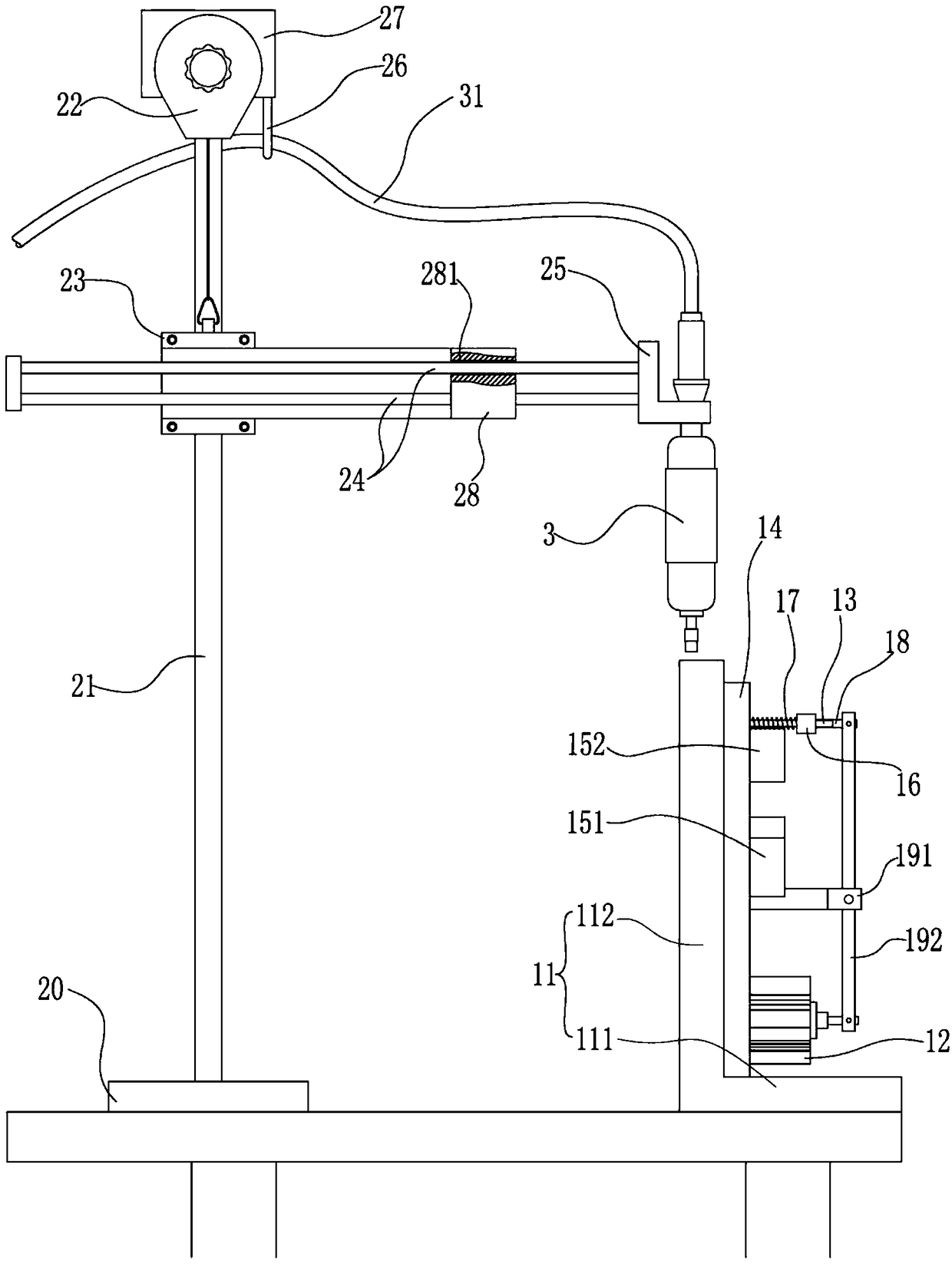
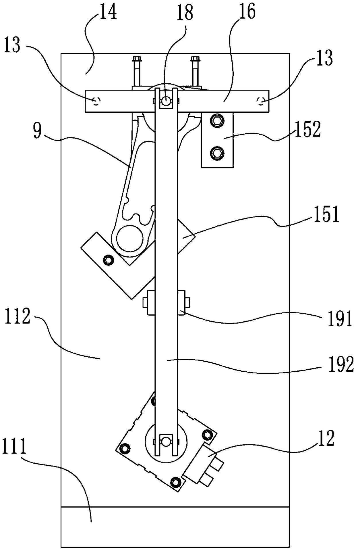
[0017] like figure 1 As shown, the present invention proposes a torque mechanism for crankshaft connecting rod production, including a clamping device, a cross bracket and a torque gun fixed on the cross bracket, wherein:

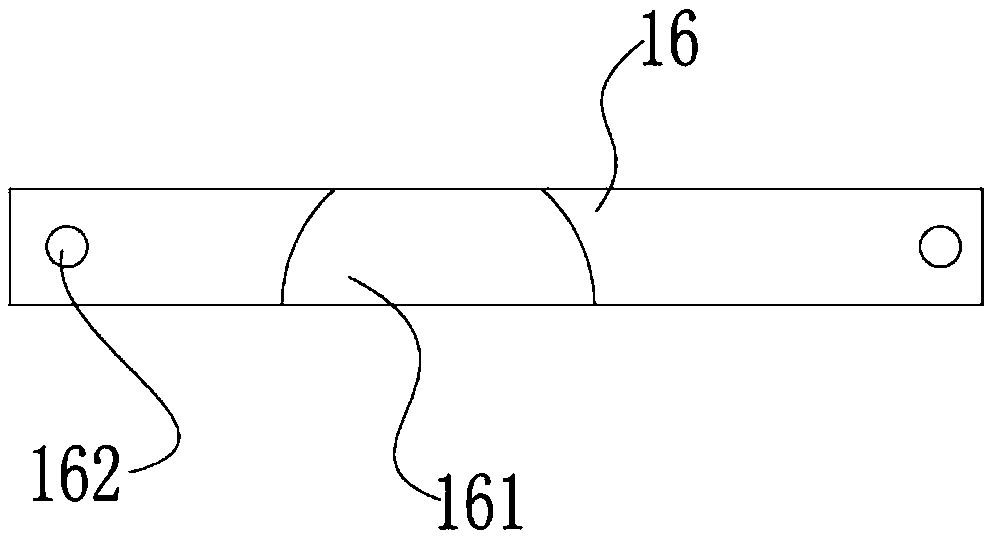
[0018] The clamping device includes a base 11, a support plate 14 vertically arranged on the base 11, a connecting rod limit seat 15 arranged on the support plate 14, a cylinder 12 arranged on the support plate, a Lever mechanism, two horizontal guide rods 13 arranged on the support plate 14, pressure blocks 16 movably sleeved on the horizontal guide rods 13, movably sleeved on the horizontal guide rods 13 and positioned between the pressure blocks 16 and the support plate 14 between the spring 17 and the pressure rod 18 connected to the side of the pressure block 16 away from the spring 17, wherein the ba...


PUM


Abstract

The invention provides a torque mechanism for crankshaft connecting rod production. The torque mechanism comprises a clamping device, a cross-shaped support and a torque gun fixed to the cross-shaped support; the clamping device comprises a base, a supporting plate arranged on the base, a connecting rod limiting base arranged on the supporting plate, an air cylinder, a lever mechanism, two horizontal guide rods, pressing blocks arranged on the horizontal guide rods in a sleeving manner, springs arranged on the horizontal guide rods in a sleeving manner and located between the pressing blocks and the supporting plate and pressing rods connected to the sides, far away from the springs, of the connecting blocks, and a stretchable rod of the air cylinder and the pressing rods are riveted with the two ends of a level; the cross-shaped support comprises a supporting base, a strut arranged on the supporting base, an installation block arranged at the top end of the strut, a lifting mechanism arranged on the installation block, a first sliding block arranged on the strut in a sleeving manner, a second sliding block fixed to the first sliding block, a horizontal sliding rod installed on the second sliding block and a lifting block arranged at one end of the horizontal sliding rod; and the torque gun is arranged on the lifting block. By means of the torque mechanism, the assembly efficiency is improved, and operation is more easy and labor-saving and safe.

Description

technical field [0001] The invention relates to the field of mechanical manufacturing, in particular to an aerodynamic torque device used in the production of crankshaft connecting rods. Background technique [0002] Crankshaft-connecting rod mechanism is a transmission mechanism widely used in engines and motors. It is used to realize the power transmission between the linear reciprocating motion of the piston and the rotary motion of the crankshaft. The connecting rod is a rod-shaped rod directly connected between the piston and the crankshaft. The structure generally includes a small end, a shaft and a large end. The small end of the connecting rod is used to connect the piston pin, the large end of the connecting rod is used to connect with the crank pin of the crankshaft, and the shaft is used to connect the small end and the large end. The big head is designed as a split type, and the separated part is the connecting rod cover. During production, the connecting rod and...

Claims


Application Information

Patent Timeline
Patent Type & Authority Patents(China)
IPC IPC(8): B25B27/14
CPCB25B27/14
Inventor 温昌明张跃
Owner 重庆昌跃机电制造有限公司
Why Eureka
Try Eureka