
Wool jetting machine

A technology of hair spraying machine and top, which is applied in textiles, papermaking, yarn, etc. It can solve the problems of excessive hair loss, increased hair loss rate, and poor output, so as to ensure a clean environment, reduce manufacturing costs, and prevent hair loss Effect

Inactive Publication Date: 2017-03-15
嘉鱼柯特纺织股份有限公司
View PDF9 Cites 5 Cited by
  • Summary
  • Abstract
  • Description
  • Claims
  • Application Information

AI Technical Summary

Problems solved by technology

[0002] Among the fancy yarns, the sprayed wool yarn is all produced in the needle barrel type. The wool in the middle of the production is all loosened by the needle wheel fiber. The hair is sprayed out in the way of negative pressure, so that the hair is easy to break when thinning the hair, which leads to problems such as uneven spraying, poor output, and single raw material
The second-generation method is to change the one-spindle machine of the hair spraying machine to be driven by five motors, so that three-color yarns can be produced, which is a great improvement in the finished product, because the needle wheel must meet the negative pressure standard. , so the speed of the motor must reach more than 7000 rpm to achieve the effect of uniform hair spraying. In this way, the probability of fiber breaking will increase, and the hair loss rate will increase accordingly. The quality cannot be guaranteed, and the output is still low.
[0003] Various solutions in industrial applications currently have the following problems: low efficiency and high labor costs; there are great restrictions on the use of raw materials, resulting in poor practicability; high energy consumption and high cost; There are too many hairs, and the production cycle is not good

Method used


Image

  • Wool jetting machine
  • Wool jetting machine

Examples


Embodiment

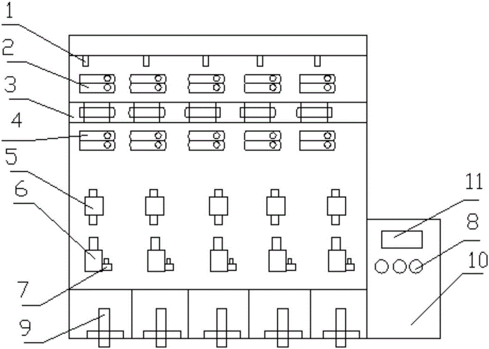
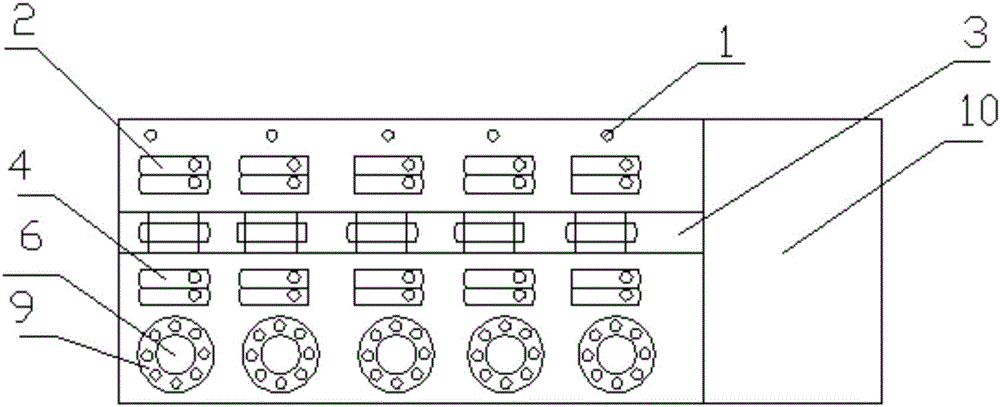
[0019] Such as figure 1 with figure 2 The hair spraying machine shown includes wool top card position 1, pressure wheel 2, air bubble pressure wheel 3, fiber sheath wheel 4, negative pressure generator 5, needle cylinder 6, motor 7, control switch 8, yarn receiving rod 9, frequency conversion The control box 10 and the display panel 11, the top clamping position 1, the pressure wheel 2, the air bubble pressure wheel 3, the fiber wheel 4, the negative pressure generator 5, the needle cylinder 6, and the yarn receiving rod 9 are arranged on the hair spraying machine from top to bottom On the frame; Motor 7 is provided with belt and is connected with syringe 6; Frequency conversion control box 10 is arranged on the frame side position of hair spraying machine;

[0020] The working process of the above hair spraying machine is as follows:

[0021] (1) Clamp the purchased wool tops on the wool top card position 1, and extend the carded wool tops to the middle of the strip feedin...


PUM


Abstract

The invention relates to a wool jetting machine. The wool jetting machine comprises wool strip clamping positions, pressing wheels, bubble pressing wheels, fiber stretching wheels, negative pressure generators, work drums, motors, control switches, yarn winding bars, a variable frequency control box and a display panel, and the wool strip clamping positions, the pressing wheels, the bubble pressing wheels, the fiber stretching wheels, the negative pressure generators, the work drums and the yarn winding bars are arranged on a rack of the wool jetting machine from top to bottom; belts are arranged on the motors and connected with the work drums; the variable frequency control box is arranged on one side of the rack of the wool jetting machine; the control switches and the display panel are arranged on the variable frequency control box. According to the wool jetting machine, the belts are driven in a joint driving mode, the power of each motor is reduced from 31 KW to 25 KW, the cost is reduced to 5,000 yuan per spindle from 7,000 yuan per spindle, energy consumption is reduced by 20%, and the cost is reduced by 30%; the soft characteristic of jet wool yarn still exists, and the wool losing and ununiform wool jetting phenomena are not prone to occur.

Description

technical field [0001] The invention relates to a hair spraying machine, which belongs to the technical field of textiles. Background technique [0002] Among the fancy yarns, the sprayed wool yarn is all produced in the needle barrel type. The wool in the middle of the production is all loosened by the needle wheel fiber. The hair is sprayed out in the way of negative pressure, so that the hair is easy to break when thinning the hair, which leads to problems such as uneven spraying, poor output, and single raw material. The second-generation method is to change the one-spindle machine of the hair spraying machine to be driven by five motors, so that three-color yarns can be produced, which is a great improvement in the finished product, because the needle wheel must meet the negative pressure standard. , so the speed of the motor must reach more than 7000 rpm to achieve the effect of uniform hair spraying. In this way, the probability of fiber breaking will increase, and t...

Claims


Application Information

Patent Timeline
Patent Type & Authority Applications(China)
IPC IPC(8): D02G3/34
CPCD02G3/34
Inventor 柯顺钦
Owner 嘉鱼柯特纺织股份有限公司
Learn More