
Performance offset-based aeroengine fault diagnosis method

A technology for aero-engine and fault diagnosis, applied in computer parts, instruments, character and pattern recognition, etc., can solve problems such as low practicability of aero-engine fault sample data

Active Publication Date: 2017-03-15
HARBIN INST OF TECH
View PDF4 Cites 27 Cited by
  • Summary
  • Abstract
  • Description
  • Claims
  • Application Information

AI Technical Summary

Problems solved by technology

[0009] The present invention aims to solve the problems that the existing technology ignores the differences between individual aeroengines, the amount of aeroengine fault sample data is small, and most of the existing methods use simulation data, resulting in low practicability, and proposes a method based on performance offset Quantitative Aeroengine Fault Diagnosis Method

Method used


Image

  • Performance offset-based aeroengine fault diagnosis method
  • Performance offset-based aeroengine fault diagnosis method
  • Performance offset-based aeroengine fault diagnosis method

Examples


specific Embodiment approach 1

[0024] Specific embodiment one: a kind of aero-engine fault diagnosis method based on performance offset comprises the following steps:

[0025] Step 1: Acquisition and grouping of aeroengine air path performance data;

[0026] Step 2: According to the grouping results of step 1, the aero-engine performance offset model is established and the performance offset is solved;

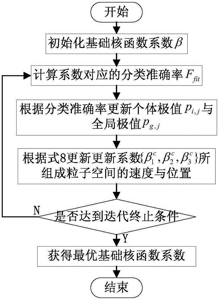
[0027] Step 3: According to the result of solving the performance offset obtained in Step 2, determine the multi-core function of the support vector machine and classify the faults.

specific Embodiment approach 2

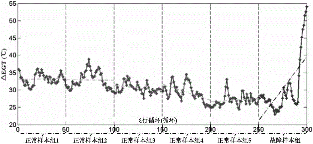
[0028] Specific embodiment two: the difference between this embodiment and specific embodiment one is that: the specific process of acquiring and grouping the air path performance data of the aeroengine in the step one is:

[0029] The air path performance parameters of aero-engines are the basis of engine fault diagnosis. The air path performance parameters of most aero-engines in service are generally transmitted to the ground in quasi-real time through the Aircraft Communications Addressing and Reporting System (ACARS). The operator of the aero-engine will sort it out and send it to the aero-engine manufacturer (Original Equipment Manufacturer, OEM), and the OEM will calculate the performance parameters. The OEM will convert the original air path performance parameters of the engine into a baseline deviation value based on the engine's working condition information, thrust setting, etc. For example: using the working condition information of the aero-engine: flight altitude...

specific Embodiment approach 3

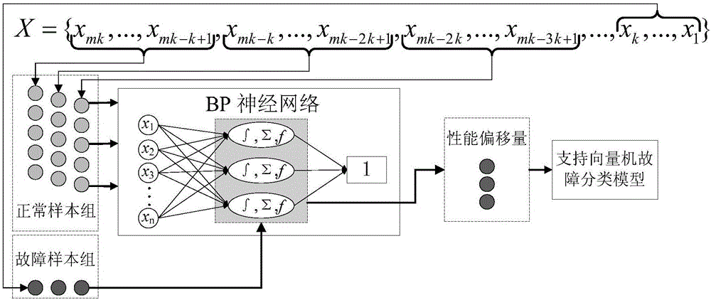
[0044] Embodiment 3: This embodiment is different from Embodiment 1 or 2 in that: the specific process of establishing the aero-engine performance offset model and solving the performance offset in the second step is:

[0045] After obtaining the normal sample data group and fault symptom data sample group of the aero-engine, the BP neural network is used to establish the performance offset calculation model of the aero-engine, the performance parameters of each normal sample group are used as the model input, and the health performance index value 1 is used as the The output expectation of the normal sample group is used to train the engine performance offset neural network; when solving the fault symptom performance offset of the current dismantling, the fault symptom sample group is used as the input of the trained offset neural network model. The output obtained through the model is the performance offset of the engine; the establishment of the performance offset model and ...


PUM


Abstract

A performance offset-based aeroengine fault diagnosis method is disclosed. The invention relates to the performance offset-based aeroengine fault diagnosis method. The performance offset-based aeroengine fault diagnosis method is used for solving a problem that individual difference between aeroengines is neglected via technologies of the prior art, aeroengine fault sample data is small in quantity and conventional methods are low in practicality due to usual adoption of simulation data. The performance offset-based aeroengine fault diagnosis method comprises the following steps: in a first step, aeroengine air passage performance data is obtained and divided into groups; in a second step, according to a grouping result of the first step, an aeroengine performance offset model is built and performance offset is obtained via solving operation; in a third step, according to a solved result of the performance offset, a support vector machine multi-kernel function can be determined and fault classification can be performed. In terms of fault classification accuracy and generalization, the performance offset-based aeroengine fault diagnosis method is better than a traditional fault diagnosis method based on time series fitting. The performance offset-based aeroengine fault diagnosis method can be applied to the technical field of aeroengine maintenance and optimization.

Description

technical field [0001] The invention relates to an aeroengine fault diagnosis method based on performance offset. Background technique [0002] Aeroengine is the core component of aircraft such as civil aviation aircraft. It is the main power source and bleed air device of the aircraft, and is compared to the "heart" of the aircraft. At the same time, an aero engine is a power machine that works in a high-speed, high-temperature, and high-pressure environment. It is a typical complex equipment that integrates machinery, electricity, and hydraulics. In the maintenance process of aero-engines, accurate diagnosis and location of engine faults can provide strong support for engine maintenance timing prediction, maintenance plan formulation, and maintenance cost estimation. [0003] With the continuous development of maintenance theory, domestic and foreign research institutions and engine manufacturers have carried out fruitful research on aeroengine fault diagnosis. At presen...

Claims


Application Information

Patent Timeline
IPC IPC(8): G06K9/62
CPCG06F18/2111G06F18/2411
Inventor 钟诗胜付旭云林琳李臻
Owner HARBIN INST OF TECH
Learn More