Infrared visual inspection device oriented to cable aging position detection
A visual detection device and cable technology, applied in image data processing, instruments, calculations, etc., can solve the problems of multiple steps, complex structure of the device, complicated operation, etc., and achieve the effect of reducing the cost and complexity of the device
- Summary
- Abstract
- Description
- Claims
- Application Information
AI Technical Summary
Problems solved by technology
Method used
Image

Examples
specific Embodiment 1
[0066] This embodiment is an embodiment of an infrared vision detection device for cable aging position detection.
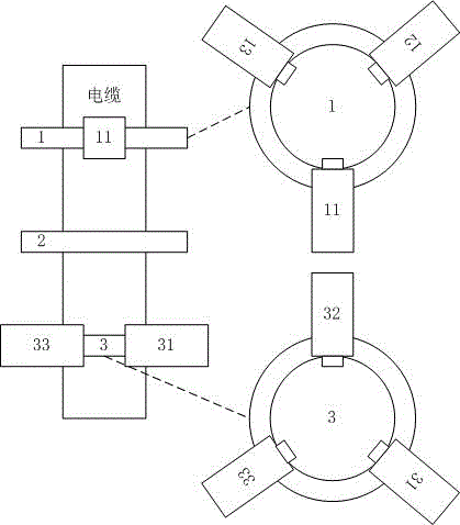
[0067] In this embodiment, the infrared visual detection device for cable aging position detection, the structural diagram is as follows figure 1 As shown, the infrared visual detection device for cable aging position detection includes an upper ring 1 without rotation function, a middle ring 2 and a lower ring 3 arranged in sequence from top to bottom, and the middle ring 2 is located on the upper ring In the middle of the ring 1 and the lower ring 3, the cable passes through the upper ring 1, the middle ring 2 and the lower ring 3; the upper ring 1 is uniformly provided with an upper infrared camera 11 and an upper second infrared camera 12 And last three infrared cameras 13; The inside of middle ring 2 is provided with the resistance wire that plays heating function; Evenly be provided with next infrared camera 31 on lower ring 3, next two infrared cameras 32...
specific Embodiment 2
[0069] This embodiment is an embodiment of an infrared vision detection method for cable aging position detection.
[0070] The infrared visual detection method for cable aging position detection in this embodiment is implemented on the infrared visual detection device for cable aging position detection described in the specific embodiment 1. The method includes the following steps:
[0071] Step a, heating the cable with the middle ring 2;
[0072] Step b, determining the aging lateral position;
[0073] Step c, determining the aging axial position;
[0074] Step d. Determine the spatial position according to the aging transverse position and axial position.
specific Embodiment 3
[0076] This embodiment is an embodiment of an infrared vision detection method for cable aging position detection.
[0077] The infrared visual detection method for cable aging position detection in this embodiment, on the basis of specific embodiment 2, further defines that step b includes the following steps:
[0078] Step b1, obtain series of grayscale data
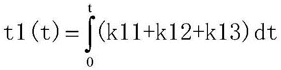
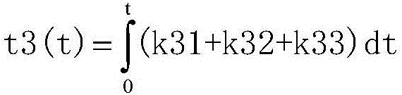
[0079] The last infrared camera 11 obtains grayscale data k11, the upper second infrared camera 12 obtains grayscale data k12, the upper third infrared camera 13 obtains grayscale data k13, the next infrared camera 31 obtains grayscale data k31, and the next second infrared camera 32 obtains grayscale data k13. Grayscale data k32, the next three infrared cameras 33 get grayscale data k33;
[0080] Step b2, combined with the lower ring 3, obtain the aging lateral position from the upper ring 1
[0081] In the upper circle 1, judge the minimum value of min(|k11-k12|,|k11-k13|,|k12-k13|), if:
[0082] The first case: |...
PUM
 Abstract
Description
Claims
Application Information
 - Generate Ideas
- Intellectual Property
- Life Sciences
- Materials
- Tech Scout
- Unparalleled Data Quality
- Higher Quality Content
- 60% Fewer Hallucinations
Browse by: Latest US Patents, China's latest patents, Technical Efficacy Thesaurus, Application Domain, Technology Topic, Popular Technical Reports.
© 2025 PatSnap. All rights reserved.Legal|Privacy policy|Modern Slavery Act Transparency Statement|Sitemap|About US| Contact US: help@patsnap.com