Optical phase retarder for measuring length of ocular axis

A technology of optical phase and axial length of the eye, applied in the direction of eye testing equipment, applications, medical science, etc., can solve the problems of complex adjustment, limited scanning range, low energy utilization rate, etc., to eliminate system dispersion and reduce scanning length , the effect of simple structure

Active Publication Date: 2017-03-22
UNIV OF SHANGHAI FOR SCI & TECH
View PDF7 Cites 2 Cited by
  • Summary
  • Abstract
  • Description
  • Claims
  • Application Information

AI Technical Summary

Problems solved by technology

[0003] In the optical coherence tomography system, the currently reported axial optical phase delay lines include: 1. Linear translation mirror, which is the simplest and longest axial scanning method; the structure is simple and the cost is low, but the main The disadvantage is that the volume is large, the running line is long, and the stability is affected by the mechanical structure; 2. The piezoelectric control parallel mirror has reliable performance and high stability, but the price is high and the scanning range is limited, which is not suitable for the eye axis length of the large scanning range Measurement; 3. Using rotating cube scanning method; scanning in this way can achieve a large scanning range, but it is difficult to install and debug, and the scanning is not linear, with dispersion and low duty cycle, which requires algorithm cooperation; 4. Rotating micromirror array , the system is nonlinear, has dispersion, has a certain duty cycle, low energy utilization rate, too complicated adjustment, high cost, and is not suitable for mass industrialization
5. Involute spiral mirror; it can realize the advantages of high speed, good linearity, simple adjustment, large scanning range, and no dispersion, but the production accuracy is too high and it is difficult to be practical
The system structure is complex, there are many components, debugging is difficult, and the cost is high.

Method used


Image

  • Optical phase retarder for measuring length of ocular axis
  • Optical phase retarder for measuring length of ocular axis
  • Optical phase retarder for measuring length of ocular axis

Examples


Embodiment Construction

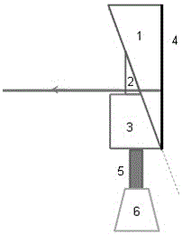
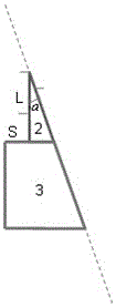
[0012] In order to achieve high stability, large scanning range, and rapid eye axial length measurement, the prism axial optical delay technology is used to realize fast scanning of the anterior segment and posterior segment of the eye, and finally achieve eye axial length measurement; the specific implementation methods are as follows: figure 1 The schematic diagram of the structure of the optical phase retarder is shown, and the axial scanning optical delay line is composed of a fixed large rectangular prism 1 and movable rectangular prisms 2 and 3; the rectangular prisms 2 and 3 are stacked up and down on a translation platform 5, The right-angled prisms 2 and 3 are moved synchronously by the translation table 5 driven by the motor 6; the right-angled prism 3 is a square or rectangular right-angled prism, and part of the small right-angled side is removed to form one side and the hypotenuse of the triangular right-angled prism 2. There are right-angled trapezoidal right-angl...


PUM


Abstract

The invention relates to an optical phase retarder for measuring the length of the ocular axis. The optical phase retarder comprises a fixed first right-angle prism and two movable right-angle prisms. The second right-angle prism and the third right-angle prism are stacked vertically and located on a transverse movement platform. The transverse movement platform is driven by a motor to move, and therefore the second right-angle prism and the third right-angle prism move synchronously. The hypotenuses of the three right-angle prisms have the same angle, thereby being in fit on a straight line. Light ray of a light source achieves incidence and penetrating through the right-angle edge of the second right-angle prism or the third right-angle prism, reaches the right-angle edge of the first right-angle prism in a vertical incidence mode through the hypotenuse of the first right-angle prism, is reflected through a high-reflection film plated on the hypotenuse of the first right-angle prism and returns back in the same way, the light source is not moved, the transverse movement platform moves, and the light ray reaches the two right-angle prisms in an incidence mode to produce the distance difference so as to achieve phase delay. Linear scanning is achieved, no aberration is introduced, the structure is simple, the cost is low, and whole-eye scanning of the anterior segment and the posterior segment of the eye is achieved.

Description

technical field [0001] The invention relates to a medical optical instrument, in particular to an optical phase retarder for eye axial length measurement. Background technique [0002] The measurement of the axial length of the eye is based on the principle of optical interference or ultrasonic detection. The optical interference method can achieve non-contact, high-resolution and fast characteristics, while the ultrasonic method needs to contact the eye, the resolution is low, and the ultrasonic probe has pressure on the eye. The accuracy of the measurement results cannot be guaranteed. In the optical interference method, partial coherence or low coherence interference technology is used, and the light source adopts a light source with a certain bandwidth and good spatial coherence. In terms of interferometry, the optical phase of the reference arm and the sample arm can only achieve interference within the coherence length of the light source. . In order to realize the m...

Claims


Application Information

Patent Timeline
Patent Type & Authority Applications(China)
IPC IPC(8): A61B3/10
CPCA61B3/10A61B3/102
Inventor 王成张大伟蔡干董肖娜项华中陈明惠郑刚
Owner UNIV OF SHANGHAI FOR SCI & TECH
Why Eureka
Try Eureka