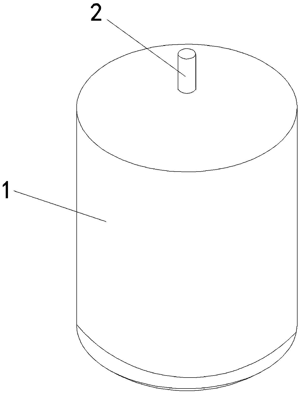
a stirrer for a reactor
A technology of agitator and reactor, which is applied in the direction of agitator accessories, chemical/physical/physicochemical fixed reactors, mixers with rotating agitating devices, etc., to achieve uniform stirring and zero residue effects
- Summary
- Abstract
- Description
- Claims
- Application Information
AI Technical Summary
Problems solved by technology
Method used
Image
Examples
Embodiment 1
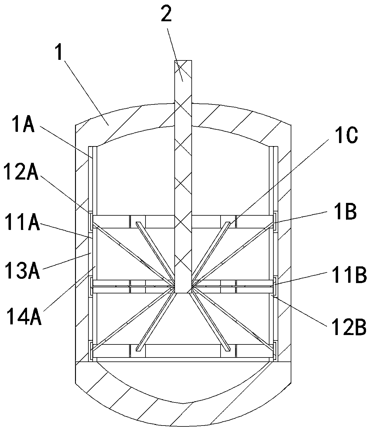
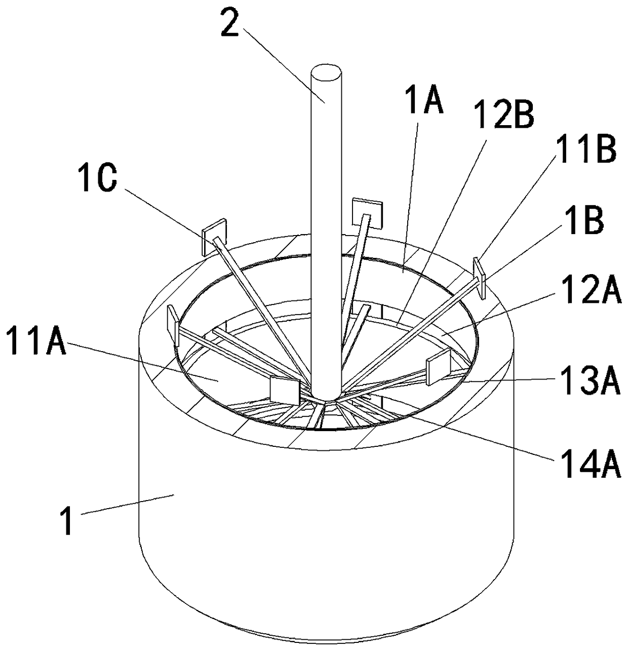
[0022] Embodiment 1, a stirrer for a reactor, comprising a reactor body 1 and a rotating shaft 2 extending into the reactor body 1, the reactor body 1 is in the shape of a pot, and the upper and lower bottom surfaces are an outwardly convex spherical surface, The lower bottom surface can be opened and closed downwards. In the middle of the upper floor, there is a rotating shaft 2 with a motor extending into the reactor body 1. The rotating shaft 2 extends from the upper bottom surface to the middle of the reactor body 1 and is fixed on the rotating shaft 2. There are stirring blades 1C, and the stirring blades 1C include upper, middle and lower layers, and each layer is provided with six stirring blades 1C. The stirring blade 1C is welded at the end of the rotating shaft 2 in a divergent shape; the upper stirring blade 1C is installed obliquely upwards, and there is an angle of 60° between it and the rotating shaft 2; the middle stirring blade 1C is arranged horizontally, perpe...
Embodiment 2
[0026] Embodiment 2, a limiting structure is provided between the end of the stirring blade 1C and the inner ring channel 12A, the limiting structure includes a limiting piece welded on the end of the stirring blade 1C and a limiting edge matched with the limiting piece, and the anti-residue smooth layer 14A constitutes bounding edge.
[0027] The stirring unit 3 welded to the rotating shaft extends from the inside to the outside of the reactor to connect with the motor, and then installs a temperature-regulating medium jacket layer 13A in the reactor body 1, and installs an anti-residue smooth layer between the temperature-regulating medium jacket layers 13A 14A, and then the temperature-regulating medium jacket layer 13A is fixedly covered with an anti-residue smooth layer 14A, and the anti-residue smooth layer 14A has the above-mentioned limited edges, and finally the lower bottom surface is closed for stirring operation. All the other structures are the same as in Embodime...
PUM
 Abstract
Description
Claims
Application Information
 - R&D
- Intellectual Property
- Life Sciences
- Materials
- Tech Scout
- Unparalleled Data Quality
- Higher Quality Content
- 60% Fewer Hallucinations
Browse by: Latest US Patents, China's latest patents, Technical Efficacy Thesaurus, Application Domain, Technology Topic, Popular Technical Reports.
© 2025 PatSnap. All rights reserved.Legal|Privacy policy|Modern Slavery Act Transparency Statement|Sitemap|About US| Contact US: help@patsnap.com


