Hydraulic control circuit and method for rotating the long nozzle clamping device of continuous casting machine

A technology of clamping device and hydraulic circuit, which is applied in the field of hydraulic control circuit for the rotation of the long nozzle clamping device of continuous casting machine, can solve the problems of automatic or flexible rotation, inconvenient long nozzle replacement or maintenance, etc., and achieves convenient burning. Oxygen scavenging, simple structure, tight fit effect

Active Publication Date: 2019-04-16
CISDI ENG CO LTD
View PDF9 Cites 0 Cited by
  • Summary
  • Abstract
  • Description
  • Claims
  • Application Information

AI Technical Summary

Problems solved by technology

[0004] In view of the above-mentioned shortcomings of the prior art, the purpose of the present invention is to provide a hydraulic control circuit and method for the rotation of the continuous casting machine shroud clamping device, which is used to solve the problem of continuous casting machine shroud clamping in the prior art. The holding device cannot be rotated automatically or flexibly, resulting in the problem of inconvenient replacement or maintenance of the shroud

Method used


Image

  • Hydraulic control circuit and method for rotating the long nozzle clamping device of continuous casting machine
  • Hydraulic control circuit and method for rotating the long nozzle clamping device of continuous casting machine
  • Hydraulic control circuit and method for rotating the long nozzle clamping device of continuous casting machine

Examples


Embodiment Construction

[0033] Embodiments of the present invention are described below through specific examples, and those skilled in the art can easily understand other advantages and effects of the present invention from the content disclosed in this specification. The present invention can also be implemented or applied through other different specific implementation modes, and various modifications or changes can be made to the details in this specification based on different viewpoints and applications without departing from the spirit of the present invention. It should be noted that, in the case of no conflict, the following embodiments and features in the embodiments can be combined with each other.

[0034] It should be noted that the diagrams provided in the following embodiments are only schematically illustrating the basic ideas of the present invention, and only the components related to the present invention are shown in the diagrams rather than the number, shape and shape of the compo...


PUM


Abstract

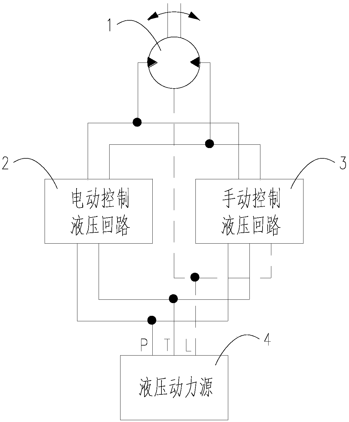
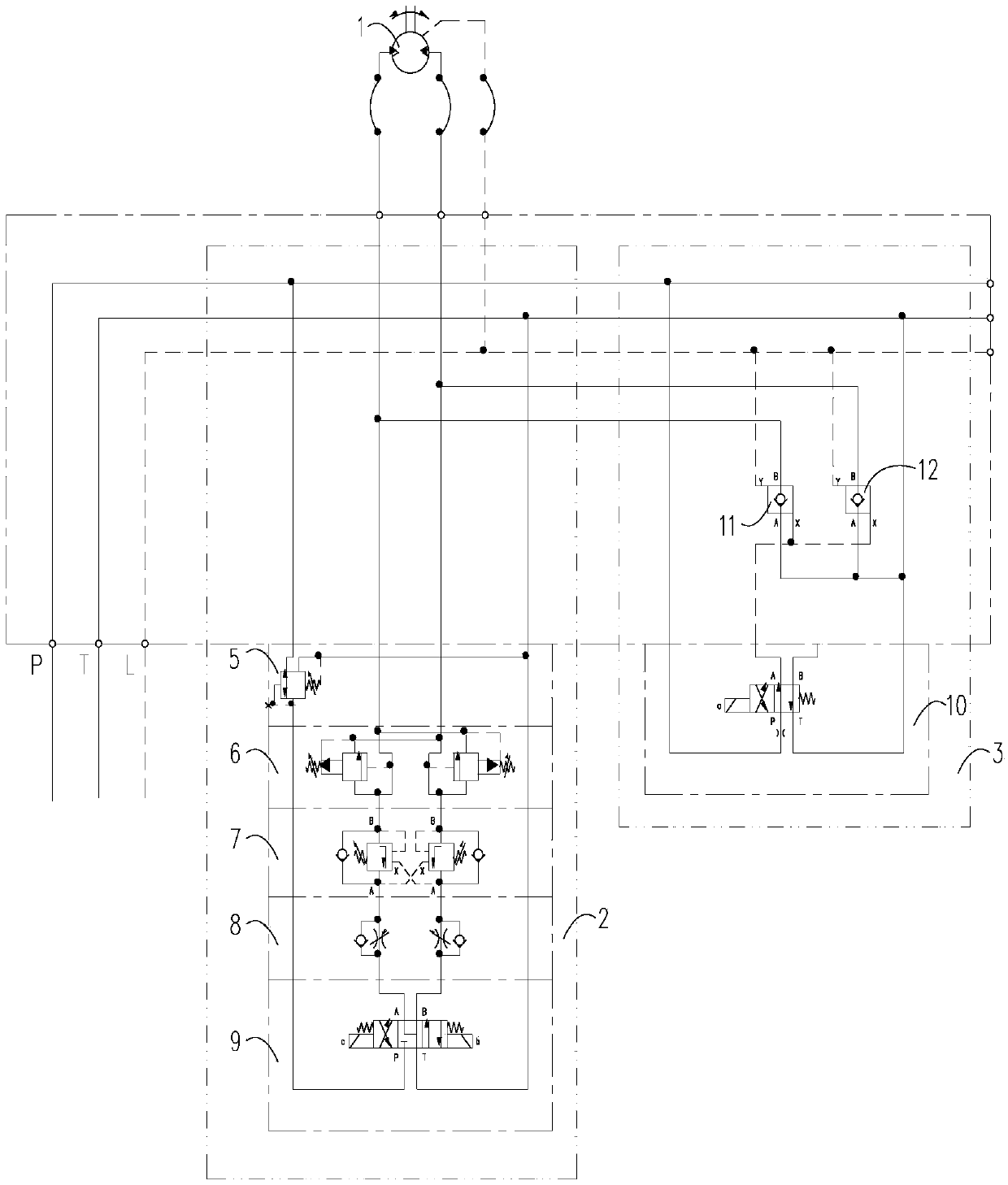
The invention provides a hydraulic control loop for rotation of a long nozzle clamping device of a continuous casting machine and a method of the hydraulic control loop. The hydraulic control loop comprises a rotation hydraulic motor and a hydraulic power source. The rotation hydraulic motor is connected with an electric control hydraulic loop and a manual control hydraulic loop which are used for controlling rotation of the rotation hydraulic motor. The electric control hydraulic loop is used for achieving inching and continuous rotation of the rotation hydraulic motor. The manual control hydraulic loop is used for unloading pressure oil of the rotation hydraulic motor when the electric control hydraulic loop is in failure, and the rotation hydraulic motor is manually rotated through a hand wheel on the long nozzle clamping device. The hydraulic control loop and the method of the hydraulic control loop have the beneficial effects that the structure is simple, operation is easy and convenient, and safety and reliability are achieved; continuous casting machine long nozzle replacing and inner cold steel burnt oxygen removing time is saved, and the production efficiency is improved. Meanwhile, a long nozzle and a sliding nozzle are attached more tightly, the possibility that air and argon are sucked into molten steel is effectively avoided, secondary oxidization of the molten steel in the casting process is prevented, and the hydraulic control loop and the method of the hydraulic control loop are suitable for occasions with the high requirement for the casting quality.

Description

technical field [0001] The invention belongs to the technical field of metallurgical engineering and relates to the technical field of hydraulic control, in particular to a hydraulic control circuit and method for rotating a long nozzle clamping device of a continuous casting machine. Background technique [0002] The long nozzle clamping device of the continuous casting machine is a device on the continuous casting machine for clamping the long nozzle and installing it to the bottom of the sliding nozzle of the steel ladle. Although the shroud clamping device is a small device on the continuous casting machine, it is also an indispensable device. The operation automation level, reliability and flexibility of the device directly affect whether the molten steel will be secondary oxidized, whether it can effectively prevent the splash of the steel stream and the personal safety of the operator, and whether the operation is convenient directly affects the operation rate of the ...

Claims


Application Information

Patent Timeline
Patent Type & Authority Patents(China)
IPC IPC(8): B22D41/56
CPCB22D41/56
Inventor 王渝李敏柏峰
Owner CISDI ENG CO LTD
Why Eureka
Try Eureka