
Milling machine

A milling machine and milling technology, applied in the field of milling machines, can solve the problems of cumbersome milling operations, easy installation of milling cutters, etc.

Active Publication Date: 2017-03-22
江苏松田数控科技有限公司
View PDF6 Cites 3 Cited by
  • Summary
  • Abstract
  • Description
  • Claims
  • Application Information

AI Technical Summary

Problems solved by technology

However, it is easy to install the milling cutter not in place
And dismounting described milling cutter frequently makes the operation of milling operation comparatively loaded down with trivial details

Method used

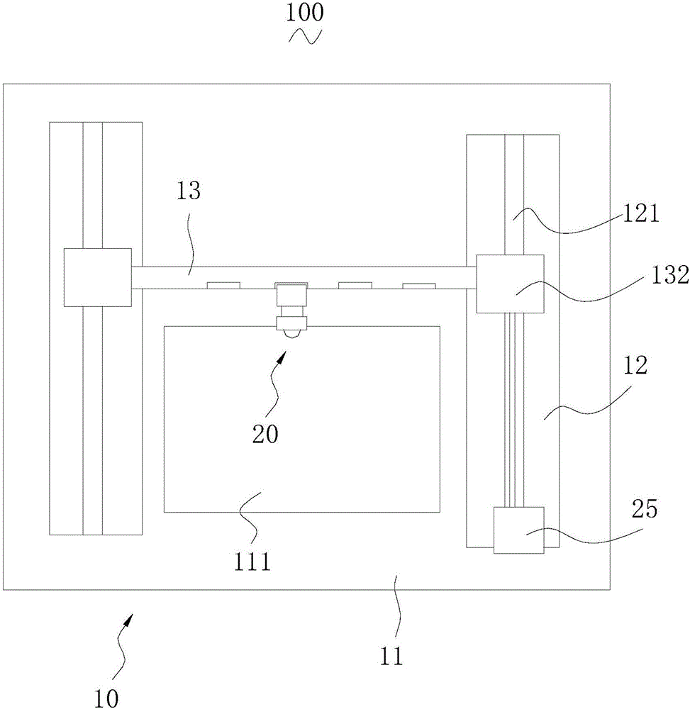
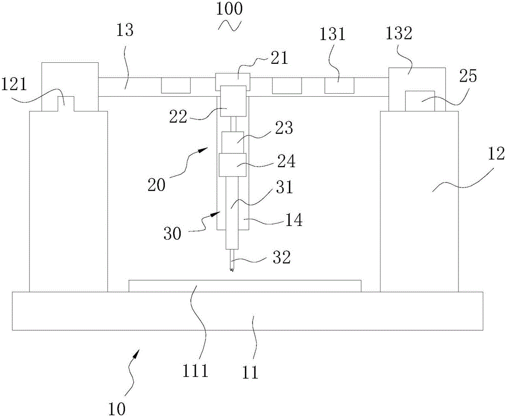
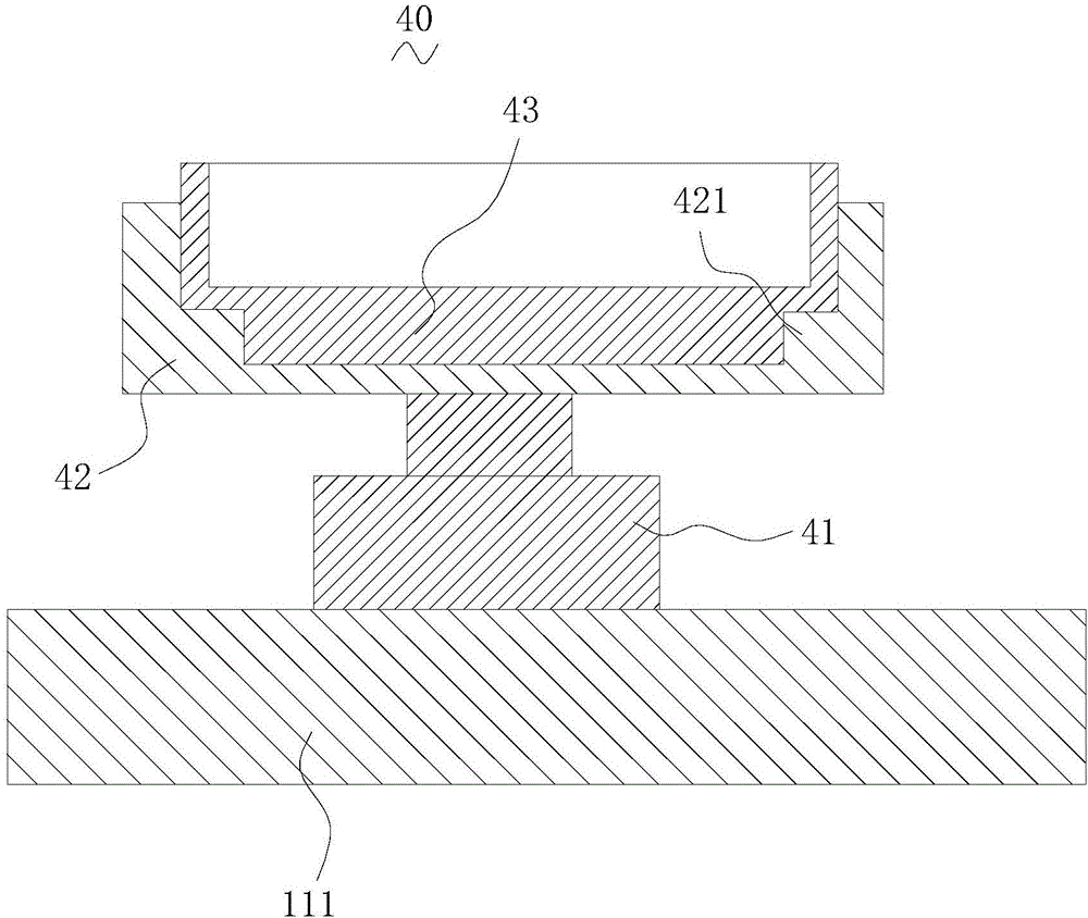

Image

  • Milling machine
  • Milling machine
  • Milling machine

Examples


Embodiment Construction

[0024] In order to make the above objects, features and advantages of the present invention more comprehensible, specific implementations of the present invention will be described in detail below in conjunction with the accompanying drawings. In the following description, numerous specific details are set forth in order to provide a thorough understanding of the present invention. However, the present invention can be implemented in many other ways different from those described here, and those skilled in the art can make similar improvements without departing from the connotation of the present invention, so the present invention is not limited by the specific implementations disclosed below.

[0025] The invention relates to a milling machine. The milling machine includes a machine base, a driving assembly and a milling assembly. The machine base includes a base, two beams and a mounting beam, and the two beams are arranged on the base at intervals. The installation beam is...


PUM

PropertyMeasurementUnit
thicknessaaaaaaaaaa
thicknessaaaaaaaaaa
thicknessaaaaaaaaaa

Abstract

The invention relates to a milling machine which comprises a machine base, a driving assembly and a milling assembly. The machine base comprises a base, two transverse beams and an installation beam, and the two transverse beams are arranged on the base in a spaced manner; the driving assembly comprises an installation block, a lifting air cylinder, a sliding block and a driving piece, and the installation beam is provided with a plurality of installation grooves; and the milling assembly comprises a main shaft and a milling cutter connected to the main shaft, and the main shaft is connected to the driving piece. The base is further provided with a closing assembly located between the two transverse beams, the closing assembly comprises a closing cylinder and a closing ring arranged at the periphery of the closing cylinder, a closing cavity is formed in the closing cylinder, and a milling cutter groove is formed in the bottom of the closing cavity. The milling cutter of the milling machine can be installed in place, and the milling process is relatively simple.

Description

technical field [0001] The present invention relates to a milling machine. Background technique [0002] In industrial production, it is often necessary to use milling machines to mill workpieces. The milling machine includes a base, a beam, a mounting beam and a milling cutter assembly, the beam is set on the base, the mounting beam is slidably set on the beam, and the milling cutter assembly is movably set on the beam on the mounting beam described above. When the milling machine is working, the mounting beam can slide relative to the beam, and the milling cutter assembly can move on the mounting beam and rotate the milling cutter therein, thereby realizing milling of workpieces. [0003] When the milling machine needs to be processed, the milling cutter is disassembled and preserved. The milling cutter needs to be installed again during the next processing. Yet install described milling cutter and be installed not in place easily. Moreover, frequent disassembly and a...

Claims


Application Information

Patent Timeline
Patent Type & Authority Applications(China)
IPC IPC(8): B23C3/00B23C9/00
CPCB23C1/00B23C1/06B23C3/00B23C9/00B23D79/02B23Q11/005B23Q13/00
Inventor 吴玲玲
Owner 江苏松田数控科技有限公司
Learn More