Connecting rod drive type clamp

A connecting rod drive and fixture technology, applied in the mechanical field

Active Publication Date: 2017-03-22
嘉兴知酷客信息科技有限公司
View PDF13 Cites 17 Cited by
  • Summary
  • Abstract
  • Description
  • Claims
  • Application Information

AI Technical Summary

Problems solved by technology

[0004] However, this kind of fixture with self-locking function cannot better realize the clamping of the workpiece

Method used


Image

  • Connecting rod drive type clamp
  • Connecting rod drive type clamp

Examples


Embodiment Construction

[0027]The following are specific embodiments of the present invention and in conjunction with the accompanying drawings, further describe the technical solution of the present invention, but the present invention is not limited to these embodiments.

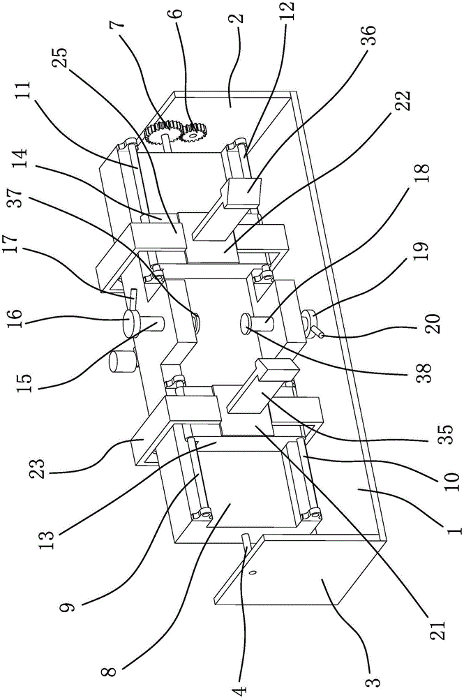
[0028] like figure 1 As shown, a link-driven clamp includes an outer frame, a clamping block one 35 , a clamping block two 36 , a clamping block three 37 and a clamping block four 38 . The outer frame comprises a base plate 1 and a vertical plate 1 and a vertical plate 2 3 fixed on the base plate 1. A rotating shaft 4 is horizontally arranged between the vertical plate 1 2 and the vertical plate 2 3. The vertical plate 1 2 is provided with a shaft that can drive the shaft 4. The rotating mechanism that rotates, the rotating mechanism includes a rotating motor 5, and the rotating motor 5 is fixed on the riser-2, and an end of the output shaft of the rotating motor 5 passing through the riser-2 is fixed with a driving gear 6, and t...


PUM


Abstract

The invention provides a connecting rod drive type clamp, and belongs to the technical field of machines. The connecting rod drive type clamp comprises an outer frame, a first clamping block, a second clamping block, a third clamping block and a fourth clamping block. The outer frame comprises a bottom plate, a first vertical plate and a second vertical plate, and a rotating mechanism is arranged on the first vertical plate. A locating frame is fixed to a rotating shaft. A first sliding rod, a second sliding rod, a third sliding rod and a fourth sliding rod are arranged on one side face of the locating frame. A first sliding block is arranged on the first sliding rod and the second sliding rod, and a second sliding block is arranged on the third sliding rod and the fourth sliding rod. A connecting rod drive mechanism is further fixed to the locating frame. A first locating plate is fixed to the locating frame and provided with a first screw. A first rotating disc is fixed to the first screw. The third clamping block is fixed to the lower surface of the first screw. A second locating plate is fixed to the locating frame and provided with a second screw. A second rotating disc is fixed to the second screw. The fourth clamping block is fixed to the lower surface of the second screw. The connecting rod drive type clamp has the beneficial effect of being capable of clamping a to-be-machined workpiece more effectively.

Description

technical field [0001] The invention belongs to the technical field of machinery, and relates to a clamp, in particular to a link-driven clamp. Background technique [0002] The fixture is a device used to fix the processing object in the process of mechanical manufacturing, so that it can occupy the correct position, and can install the workpiece quickly, conveniently and safely. For example, fixtures, inspection fixtures, assembly fixtures, machine tool fixtures, etc. Among them, machine tool fixtures are the most common and are often referred to as fixtures. When machining a workpiece on a machine tool, in order to make the surface of the workpiece meet the technical requirements such as the size, geometric shape, and position accuracy with other surfaces specified in the drawing, the workpiece must be positioned and clamped before processing. Fixtures are usually composed of positioning elements, clamping devices, tool setting guide elements, indexing devices, connectin...

Claims


Application Information

Patent Timeline
Patent Type & Authority Applications(China)
IPC IPC(8): B23Q3/06
CPCB23Q3/06
Inventor 肖俊建汤剑
Owner 嘉兴知酷客信息科技有限公司
Why Eureka
Try Eureka