Sucking nozzle of injection molding sucker

A material suction nozzle and material suction machine technology, which is applied in the field of injection molding equipment parts and injection molding suction machine suction nozzle, can solve the problems of unsteady transportation of raw materials, blockage of feeding materials, and shortage, etc., to reduce the number of injection molding machines, The effect of stable feeding and avoiding pits

Inactive Publication Date: 2017-03-22
BISHAN BRANCH OF CHONGQING RUNTONG IND CO LTD
View PDF0 Cites 0 Cited by
  • Summary
  • Abstract
  • Description
  • Claims
  • Application Information

AI Technical Summary

Problems solved by technology

[0002] Injection molding raw materials are mostly fine particles, and the injection molding process usually uses suction to add raw materials into the funnel of the injection molding machine. The suction nozzle of ordinary raw material suction equipment is too simple, which often produces defects such as blockage or insufficient feeding, and cannot transport raw materials smoothly.

Method used


Image

  • Sucking nozzle of injection molding sucker
  • Sucking nozzle of injection molding sucker

Examples


Embodiment Construction

[0015] Hereinafter, preferred embodiments of the present invention will be described in detail with reference to the accompanying drawings.

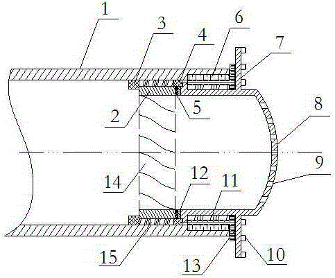
[0016] Such as figure 1 As shown, the suction nozzle of the injection molding suction machine of the present embodiment, the suction nozzle of the injection molding suction machine includes a suction pipe 1, and also includes a rotary suction mechanism and a rotary drive mechanism, and the rotary drive mechanism is arranged on the suction pipe. 1, one end of the rotary suction mechanism is located in the suction pipe 1 and is in contact with the rotary drive mechanism, and the other end is located outside the suction pipe 1; the rotary drive mechanism includes a cylindrical outer shell 2 and is installed inside the outer shell 2 The turbine blade 14, the outer wall of the outer casing 2 is in contact with the inner wall of the suction pipe 1 and can rotate freely around its axis, the right end of the cylindrical outer casing 2 is provide...


PUM


Abstract

The invention discloses a sucking nozzle of an injection molding sucker. The sucking nozzle of the injection molding sucker comprises a sucking pipe, and further comprises a rotary sucking mechanism and a rotary driving mechanism; the rotary driving mechanism is arranged in the sucking pipe; one end of the rotary sucking mechanism is positioned in the sucking pipe and is in contact with the rotary driving mechanism, and the other end is positioned out of the sucking pipe; the rotary driving mechanism includes a cylindrical outer shell and a turbofan blade mounted in the outer shell; the outer wall of the outer shell is in contact with the inner wall of the sucking pipe, and can freely rotate around the axis thereof; a gear ring I is arranged on the right end surface of the cylindrical outer shell; the rotary sucking mechanism includes a cylindrical section sleeved with the sucking pipe, and an external sucking disc; the outer wall of the cylindrical section is matched with the inner wall of the sucking pipe, and can freely rotate around the axis of the sucking pipe; a gear ring II engaged with the gear ring I is arranged on the left end surface of the cylindrical section; the sucking disc is projected rightwards, and is provided with multiple stirring support rods on the peripheral surface; a feed hole is formed in the sucking disc; and stirring teeth are arranged on the stirring support rods. The sucking nozzle can realize stable feeding.

Description

technical field [0001] The invention relates to the technical field of plastic molding, relates to a component of injection molding equipment, in particular to a suction nozzle of an injection molding suction machine used for fine suction of injection molding raw materials. Background technique [0002] Injection molding raw materials are mostly fine particles, and the injection molding process usually uses suction to add raw materials into the funnel of the injection molding machine. The suction nozzle of ordinary raw material suction equipment is too simple, which often produces defects such as blockage or insufficient feeding, and cannot transport raw materials smoothly. Contents of the invention [0003] In view of this, the invention provides a suction nozzle of an injection molding suction machine. [0004] The suction nozzle of the injection molding suction machine includes a suction pipe, and also includes a rotary suction mechanism and a rotary drive mechanism. Th...

Claims


Application Information

Patent Timeline
IPC IPC(8): B29C45/18
CPCB29C45/18
Inventor 李向东
Owner BISHAN BRANCH OF CHONGQING RUNTONG IND CO LTD
Why Eureka
Try Eureka