
Automatic management cabinet and management method for machine tool cutter

A technology for automatic management and knives, applied in transportation, packaging, storage devices, etc., can solve the problems of surprising waste of knives, opaque data of knives, error-prone, etc., to avoid borrowing and misappropriation, avoid inconsistent accounts, and reduce production costs Effect

Active Publication Date: 2017-03-22
SHENZHEN FLYTA TECH DEV
View PDF14 Cites 7 Cited by
  • Summary
  • Abstract
  • Description
  • Claims
  • Application Information

AI Technical Summary

Problems solved by technology

The problems in the management and use of enterprise tools are also reflected in: there are many departments using tool data, the tool data is not transparent, and the tool data cannot realize real data sharing, resulting in low work efficiency of enterprise tool users and frequent duplication of work
At the company level, the cost of tool inventory is high, and the waste of tool use on the production site is astonishing; the management cannot control the use of tools; the process technology department and the production site cannot check the tool inventory in time
Enterprise knives lack basic data management. Due to the wide variety of knives and the huge quantity, most of the knives warehouse administrators use ledger management or EXCEL form for bookkeeping management. The data security is poor, the labor efficiency is low, and it is easy to make mistakes. , the workload of the warehouse manager is very heavy

Method used


Image

  • Automatic management cabinet and management method for machine tool cutter
  • Automatic management cabinet and management method for machine tool cutter
  • Automatic management cabinet and management method for machine tool cutter

Examples


Embodiment 2

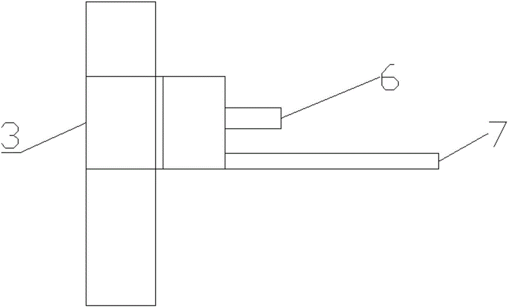
[0055]Embodiment 2 is different from Embodiment 1 in that the cutter moving device 3 is also provided with a cutter placement plate 7 for placing the cutter, and the cutter placement plate 7 is arranged below the push rod 6. Under the control of the controller, The tool placed on the plate can be pushed into the compartment of the tool storage device 2 via the push rod 6 . Through this setting, this product can realize the function of automatic tool return. Specifically, when the user returns the tool, place the tool that should be returned on the tool placement plate 7, and obtain the tool code by scanning the identification code on the tool packaging tube or according to the user’s The tool code is manually input, and the controller automatically controls the tool moving device to move to the grid at the corresponding position. At this time, the tool placement plate 7 is smoothly docked with the lower surface of the grid position, and the controller controls the push rod 6 to...


PUM


Abstract

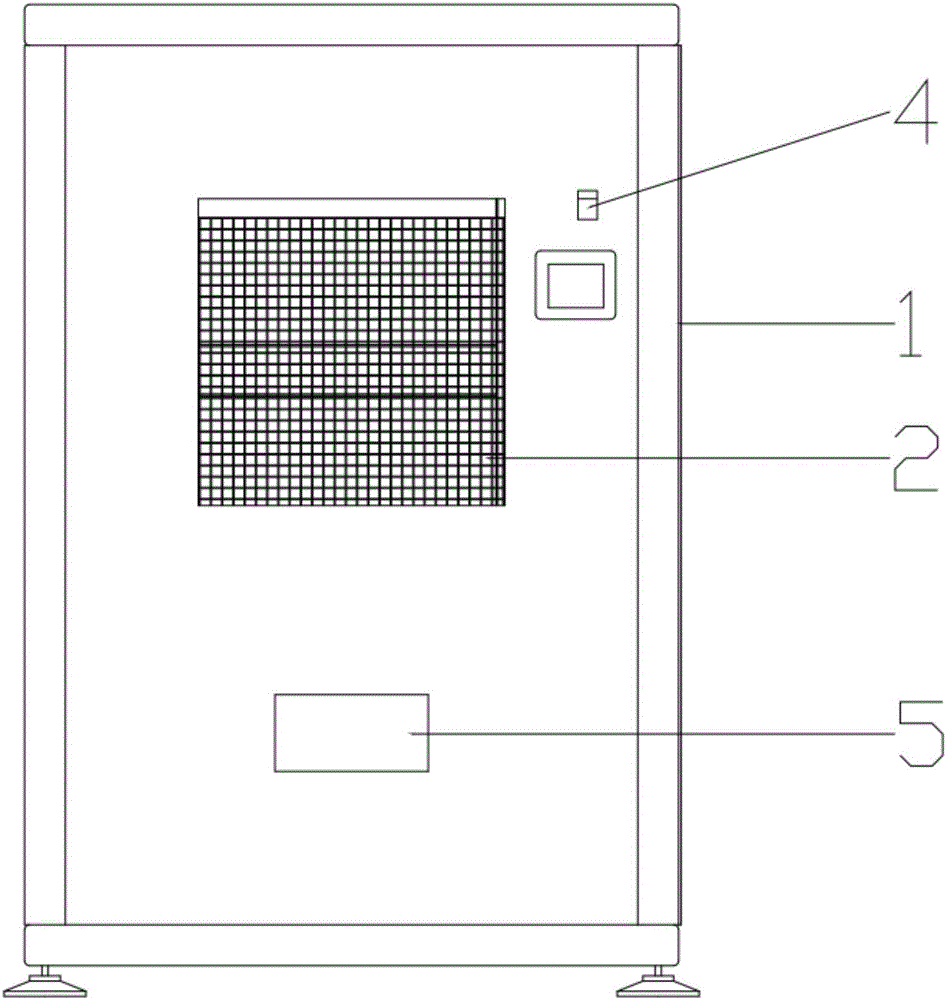
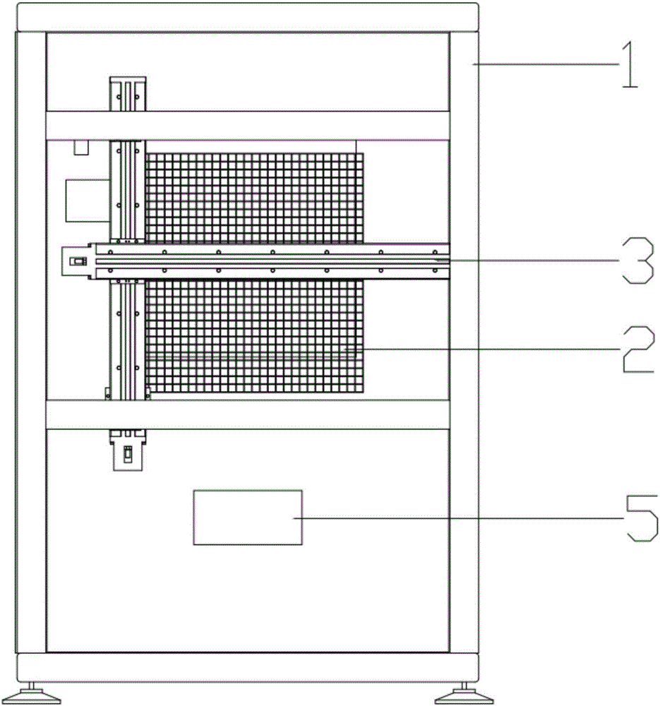
The invention relates to the field of machine tool cutter management, in particular to an automatic management cabinet and a management method for a machine tool cutter. The automatic management cabinet for the machine tool cutter comprises a cabinet body, a cutter storage device which is mounted on the cabinet body, a cutter moving device which is arranged on the front side or the rear side of the cutter storage device, and a control system which is used for controlling the cutter moving device to move to a specified position and take a cutter at the specified position; the cutter storage device is of a grid structure of which the front part and the rear part are communicated with each other; the cutter moving device comprises a moving platform and a push rod which is connected with the moving platform; the push rod can move randomly in a grid area in the cutter storage device under the driving of the moving platform, and can push an object which is stored in a grid out of the grid through the stretching and retracting of the push rod. According to the automatic management cabinet and the management method for the machine tool cutter, the cutter can be taken and returned automatically; meanwhile, the functions of automatically detecting and recording the storage conditions of the cutter can also be realized; manpower resources can be saved; the situation of inconsistency between accounts and real numbers is avoided.

Description

technical field [0001] The invention relates to the field of machine tool tool management, in particular to an automatic machine tool tool management cabinet and a management method thereof. Background technique [0002] As an important auxiliary tool for modern machinery manufacturing enterprises, cutting tools are also a relatively expensive consumable resource, which has the characteristics of many specifications, large quantities, complex information, frequent use, and high loss rate. Due to the needs of processing, a large number of tools frequently flow and exchange in the system. When the system needs to be reorganized, the configuration and capacity of the tools need to be modified. Therefore, a large number of tool information is also constantly changing. The management of cutting tools brings great difficulties, and the lack of effective management of cutting tools will directly affect the production efficiency and manufacturing costs of enterprises. According to ...

Claims


Application Information

Patent Timeline
Patent Type & Authority Applications(China)
IPC IPC(8): B65G1/137B65G1/02
CPCB65G1/02B65G1/1371
Inventor 周杰李峻龚军祥彭良群舒宗昊张赟
Owner SHENZHEN FLYTA TECH DEV
Learn More