
Product protection circuit for achieving high voltage restraining during engine load dump

A technology for engine load and high pressure suppression, which is applied in the direction of engine starting, engine components, machines/engines, etc., to achieve the effect of small pressure drop and cost reduction

Inactive Publication Date: 2017-03-22
CURTIS TECH SUZHOU
View PDF5 Cites 0 Cited by
  • Summary
  • Abstract
  • Description
  • Claims
  • Application Information

AI Technical Summary

Problems solved by technology

[0004] The purpose of the present invention is to provide a product protection circuit that adopts discrete components to realize high voltage suppression when the engine load suddenly drops, and overcomes the defects of the existing load sudden drop protection circuit

Method used

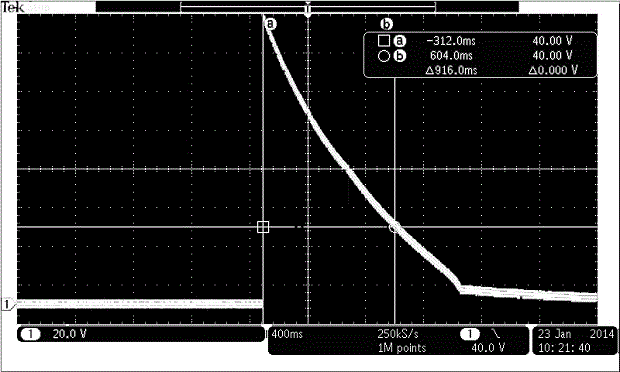
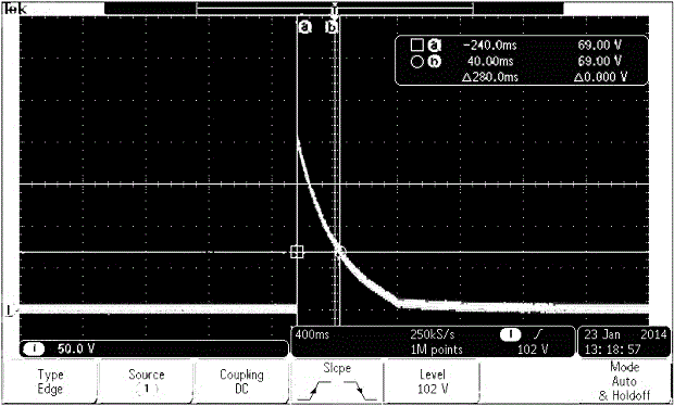

Image

  • Product protection circuit for achieving high voltage restraining during engine load dump
  • Product protection circuit for achieving high voltage restraining during engine load dump
  • Product protection circuit for achieving high voltage restraining during engine load dump

Examples


Embodiment Construction

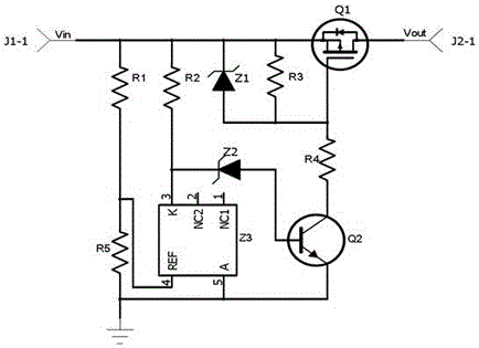
[0018] Such as figure 1 As mentioned above, the product protection circuit for realizing high-voltage suppression when the engine load suddenly drops disclosed in the present invention includes resistors R1-R5, voltage regulator tubes Z1-Z2, voltage reference source TL431, PMOS transistor Q1 and transistor Q2, wherein TL431 is composed of Z3 Mark, the source of the PMOS transistor Q1 is connected to the power input terminal Vin, the drain is used as the power output terminal Vout, and the gate is grounded through the resistor R4 and the transistor Q2 in turn; the resistors R1 and R5 are connected in series between Vin and the ground to form a voltage dividing sampling circuit , the sampling voltage output is connected to the REF terminal of TL431, the anode of TL431 is grounded, the cathode is respectively connected to Vin through resistor R2, and the base of transistor Q2 is connected through regulator Z2, and the power input terminal Vin is also connected through parallel reg...


PUM


Abstract

The invention discloses a product protection circuit for achieving high voltage restraining during engine load dump. The product protection circuit comprises a resistor R1, a resistor R2, a resistor R3, a resistor R4, a resistor R5, a voltage-regulator tube Z1, a voltage-regulator tube Z2, a voltage reference TL431, a PMOS tube Q1 and a transistor Q2, wherein the source electrode of the PMOS tube Q1 is connected with a power source input end Vin, the drain electrode of the PMOS tube Q1 serves as a power source output end Vout, and the grid electrode of the PMOS tube Q1 is grounded through resistor R4 and the transistor Q2 in sequence; the resistor R1 and the resistor R5 are connected between the power source input end Vin and the ground in series to form a partial voltage sampling circuit, the sampling voltage is in output connection with the REF end of the voltage reference TL431, the positive pole of the voltage reference TL431 is grounded, and the negative pole of the voltage reference TL431 is connected with the power source input end Vin through the resistor R2 and connected with the base electrode of the PMOS tube Q1 through the resistor R3; and the power source input end Vin is further connected with the grid electrode of the PMOS tube Q1 through the voltage-regulator tube Z1 and the resistor R3 which are connected in parallel. By means of the product protection circuit for achieving high voltage restraining during engine load dump through discrete components, the cost is effectively reduced, the voltage drop of the power source output end Vout is far more smaller than the voltage drop of the power source input end Vin, and normal work can be done under the condition that the voltage of a battery is very low.

Description

technical field [0001] The invention relates to engine protection, in particular to a product protection circuit which adopts discrete components to realize high voltage suppression when the engine load suddenly drops. Background technique [0002] The engine will have a load dump phenomenon at the moment of starting. This load dump will generate a very high voltage instantaneously. If the product cannot suppress this high voltage, it will cause great damage to the product, and sometimes even lead to major accidents. [0003] In order to achieve the purpose of suppressing this high voltage, the traditional method is to use a transient voltage suppression diode (TVS) for protection. If only the TVS tube is used, because the TVS tube needs to be able to absorb a huge amount of energy in an instant, it is necessary to choose The high-power TVS tube can achieve the goal, which will greatly increase the cost of the product; another method is to connect a resistor in series betwe...

Claims


Application Information

Patent Timeline
IPC IPC(8): F02B77/08F02N15/10
CPCF02B77/08F02N15/10
Inventor 刘明达
Owner CURTIS TECH SUZHOU
Learn More