Flow control electromagnetic valve

A flow control and solenoid valve technology, applied in the direction of valve lift, valve details, valve device, etc., can solve the problems of unsuitable macro-adjustable working conditions, poor reliability, complex structure, etc., and achieve simple structure, stable flow, and simple control Effect

Active Publication Date: 2017-03-22
XIAN AEROSPACE PROPULSION INST
View PDF6 Cites 9 Cited by
  • Summary
  • Abstract
  • Description
  • Claims
  • Application Information

AI Technical Summary

Problems solved by technology

[0003] The technical problem to be solved by the present invention is to provide a flow control solenoid valve to solve the defects in the prior art that the structure is complex, the reliability is poor, and it is not suitable for macroscopically adjustable working conditions.

Method used


Image

  • Flow control electromagnetic valve
  • Flow control electromagnetic valve
  • Flow control electromagnetic valve

Examples


Embodiment Construction

[0015] The present invention will be described in detail below in conjunction with specific embodiments and accompanying drawings.

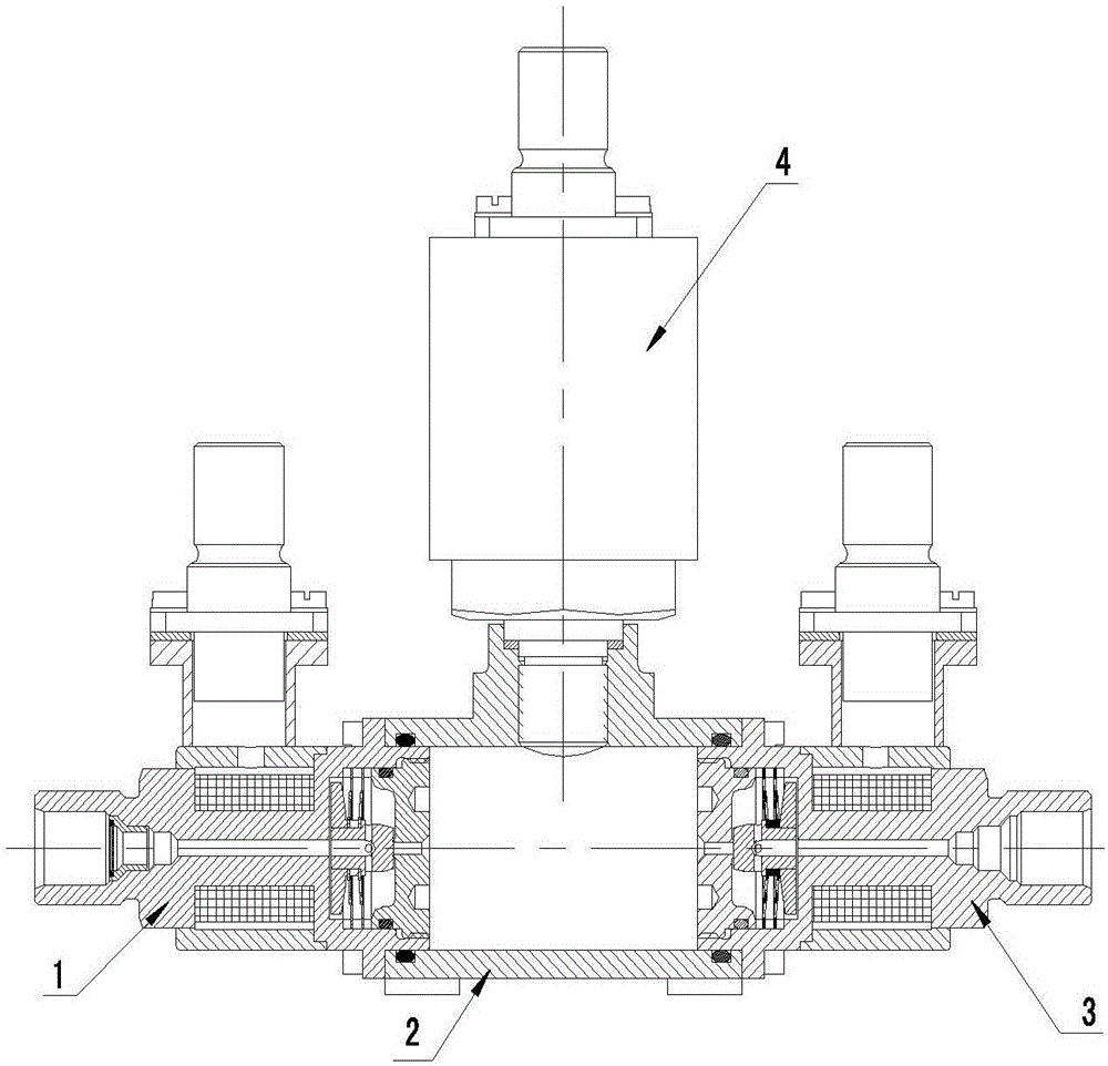
[0016] like figure 1 As shown, the present invention provides a flow control solenoid valve, including a first frictionless solenoid valve 1 , a cavity base 2 , a second frictionless solenoid valve 3 , and a pressure sensor 4 . The first frictionless solenoid valve 1 and the second frictionless solenoid valve 3 are symmetrically installed on both sides of the cavity base 2 through a square flange. When work is required, the first frictionless solenoid valve 1 is energized first, and the valve core 9 overcomes the medium force and frictional force movement, open the medium inlet, and the upstream medium pressurizes the cavity base 2; then the first frictionless solenoid valve 1 is de-energized, the medium inlet is closed, the second frictionless solenoid valve 3 is energized, the medium outlet is opened, and the cavity The medium in the medium is...


PUM


Abstract

The invention aims to achieve the technical effect of providing a flow control electromagnetic valve which can overcome the defects that in the prior art, structures are complex, the reliability is poor, and valves are not suitable for macroscopical adjustable working conditions. The flow control electromagnetic valve comprises a cavity substrate, a first electromagnetic valve body and a second electromagnetic valve body. The first electromagnetic valve body and the second electromagnetic valve body are arranged on the two sides of the cavity substrate correspondingly. A medium enters the cavity substrate through the first electromagnetic valve body and then flows out of the second electromagnetic valve body. Due to the fact that the friction-free electromagnetic valve combination is adopted for flow control, sliding abrasion between a valve element and a guiding face of a traditional direct operated type electromagnetic valve is completely avoided, the service life of the electromagnetic valve is greatly prolonged, and compared with traditional flow control valves, the electromagnetic valve is simple in structure, easy to control, stable in flow, reliable in operation, long in service life and good in economical efficiency.

Description

technical field [0001] The invention belongs to the field of electromechanical engineering, in particular to a flow control solenoid valve. Background technique [0002] Traditional flow control valves adjust the medium flow by changing the area of ​​the orifice. The driving mechanism generally chooses torque motors, motors, etc. This type of flow control valve has the characteristics of high flow adjustment accuracy and good linearity, but its structure is relatively Complex, difficult to control, poor economy. Traditional flow control valves are not suitable for some application fields that only require macroscopically adjustable and stable flow, simple product structure, simple control, reliable operation, long service life, and good economy. Contents of the invention [0003] The technical problem to be solved by the present invention is to provide a flow control solenoid valve to solve the defects in the prior art that the structure is complex, the reliability is poo...

Claims


Application Information

Patent Timeline
Patent Type & Authority Applications(China)
IPC IPC(8): F16K1/36F16K31/06F16K37/00
CPCF16K1/36F16K31/0624F16K37/005
Inventor 雷小飞赵双龙曾维亮袁洪滨沙超徐登伟孙磊
Owner XIAN AEROSPACE PROPULSION INST
Why Eureka
Try Eureka