Swirling piece, swirling burner and manufacturing method of swirling burner

A swirl burner and manufacturing method technology, applied in the direction of combustion method, burner, gas fuel burner, etc., can solve the problem of large pressure loss, achieve the effects of stable flow, simplify the installation process, and alleviate noise pollution

Active Publication Date: 2017-03-22
ANHUI CHENGMING HEAT ENERGY TECH
View PDF11 Cites 4 Cited by
  • Summary
  • Abstract
  • Description
  • Claims
  • Application Information

AI Technical Summary

Problems solved by technology

[0005] The above two applications, like most of the swirling combustion equipment in the prior art, use the swirling flow generated by the swirling vanes to improve the combustion effect, but the swirling vanes produced in the prior art are effective for the high-speed flow of fuel and air. When conducting flow diversion, the pressure loss is relatively large. Therefore, how to effectively reduce the pressure loss after the high-speed flowing fuel and air pass through the swirl plate has always been a technical problem that needs to be solved urgently in this field.

Method used


Image

  • Swirling piece, swirling burner and manufacturing method of swirling burner
  • Swirling piece, swirling burner and manufacturing method of swirling burner
  • Swirling piece, swirling burner and manufacturing method of swirling burner

Examples


Embodiment 1

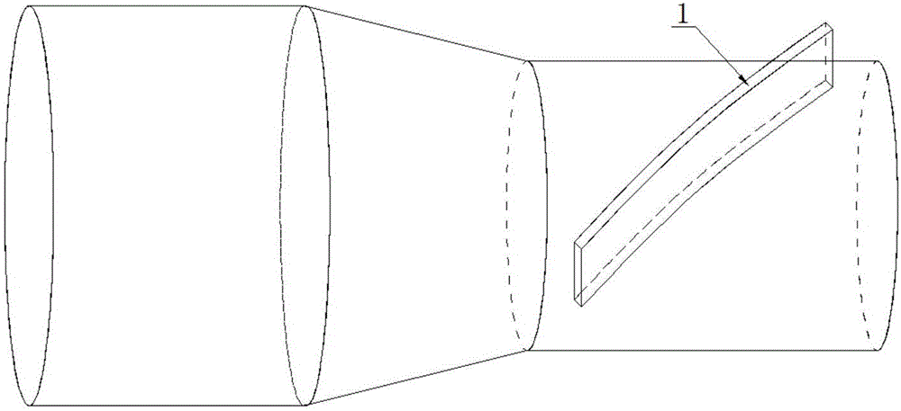
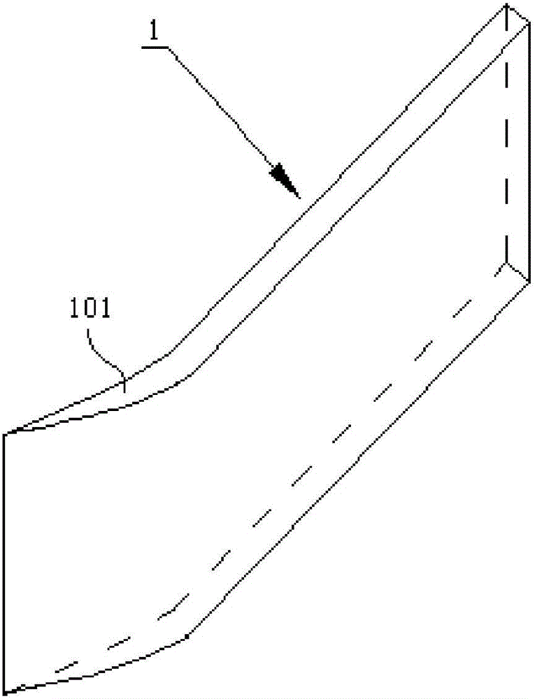
[0043] refer to figure 2 , the swirl sheet 1 of the present embodiment comprises a swirl sheet body, one end of the swirl sheet body is provided with a windward section 101, and the other end is provided with a windward section 102, and the fluid flows from the windward section 101 to the windward section 102; The thickness of the segment 101 gradually increases along the flow direction of the fluid until it is the same as the thickness of the swirl vane body.

[0044]Most of the swirl combustion equipment in the prior art uses the swirl generated by the swirl sheets to enhance the combustion effect, but the swirl sheets produced in the prior art can guide the fluid, especially the high-speed flowing fuel or air , The pressure loss is large, which not only increases the power consumption of the blower, but also affects the efficiency of the burner. In the prior art, it is generally believed that the mechanism of high pressure loss after the high-speed fluid passes through th...

Embodiment 2

[0047] refer to figure 2 , the structure of the swirl sheet 1 of the present embodiment is basically the same as that of embodiment 1, the difference is that in the design process, the ratio between the length of the windward section 101 and the length of the entire swirl sheet should be adjusted, the present embodiment Among them, the length of the windward section 101 is 0.05 to 0.9 times the length of the entire swirl vane, so as to adapt to different design conditions (specifically, 0.05 is taken in this embodiment); theoretically, the windward section 101 is far away from one end of the swirl vane body. The thinner the thickness, the better the diversion effect of the high-speed fluid, and the more it can reduce the impact pressure drop of the high-speed fluid. However, in the actual processing of the swirl sheet in this embodiment, the thickness of the windward section 101 away from the end of the swirl sheet body can be designed. It is 0.01 to 0.25 times the thickness ...

Embodiment 3

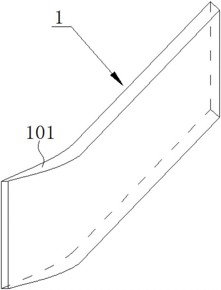
[0049] refer to Figure 4 , the structure of the swirl sheet 1 of the present embodiment is basically the same as that of embodiment 2, the difference is that the thickness of the contact between the air outlet section 102 and the swirl sheet body is the same as the thickness of the swirl sheet body, and the air outlet section The thickness of 102 tapers in the direction of fluid flow.

[0050] In this embodiment, the thickness of the air outlet section 102 is designed to be tapered along the flow direction of the fluid, so that when the high-speed fluid flows out along the air outlet section 102, it forms a good guiding effect on the outflowing high-speed fluid, and enhances the final formation of swirling flow. stability.


PUM


Abstract

The invention discloses a swirling piece, a swirling burner and a manufacturing method of the swirling burner and relates to the field of swirling combustion equipment adopting the swirling piece. The swirling piece comprises a swirling piece body. An against-wind section is arranged at one end of the swirling piece body, and a wind outlet section is arranged at the other end of the swirling piece body. Fluid flows towards the wind outlet section from the against-wind section. The thickness of the against-wind section is gradually increased in the flowing direction of the fluid till being the same as that of the swirling piece body. The swirling burner comprises an inner pipeline, an outer pipeline, one swirling piece arranged on the inner wall of the inner pipeline, one swirling piece arranged on the outer wall of the inner pipeline and/or one swirling piece arranged on the inner wall of the outer pipeline, wherein, the inner pipeline is sleeved with the outer pipeline. According to the swirling piece, the swirling burner and the manufacturing method of the swirling burner, pressure loss after the high speed fluid passes through the swirling piece can be reduced by the swirling piece and the swirling burner at low cost, and the mounting procedure of the swirling piece can be greatly simplified through the manufacturing method of the swirling burner.

Description

technical field [0001] The invention relates to the field of swirl combustion equipment using swirl vanes, and more specifically relates to a swirl vane, a swirl burner and a manufacturing method thereof. Background technique [0002] No matter what kind of gas is burned, air is needed to support the combustion. The mixing ratio and mixing degree of gas and air determine the degree of combustion of gas. The more fully the gas is burned, the higher the calorific value it produces, and the least waste gas and harmful gas are produced after combustion, so as to achieve the goals of high efficiency, energy saving and environmental protection. In the prior art, some gas combustion heads are equipped with swirlers. After the combustion-supporting air is sucked out by the burning flame along the blades of the swirlers, on the one hand, it further promotes the combustion of the gas, and on the other hand, it can make the flames rotate and diffuse during combustion. Expand the burni...

Claims


Application Information

Patent Timeline
Patent Type & Authority Applications(China)
IPC IPC(8): F23D14/02F23D14/70
CPCF23D14/02F23D14/70
Inventor 丁长永陈光薛华飞王恒达
Owner ANHUI CHENGMING HEAT ENERGY TECH
Why Eureka
Try Eureka