A rotary biofuel combustion furnace

A biofuel and combustion furnace technology, applied in the direction of rotary grate, combustion equipment, combustion method, etc., can solve the problems of frequent ash discharge, affecting combustion, and difficult operation of ash discharge, so as to improve combustion efficiency, save energy, and discharge Ash quick and easy effect

Active Publication Date: 2019-02-12
CHONGQING HUAWANLUN BIOLOGICAL NEW ENERGY TECH CO LTD
View PDF3 Cites 1 Cited by
  • Summary
  • Abstract
  • Description
  • Claims
  • Application Information

AI Technical Summary

Problems solved by technology

my country is a large agricultural country, and a large amount of straw is burned in the farmland every year. The heat energy of the straw cannot be fully utilized, mainly because the energy per unit volume of the straw is too low, resulting in burning and discarding. In order to make full use of the straw to solve the above problems, Our country vigorously advocates remaking straw into biofuel. Now it is mainly crushed and pressed into high-density particles to increase the heat energy per unit volume. The rear airflow is not smooth, which affects combustion, and the amount of burnt ash is large, and the accumulation of ash also affects combustion. The ash discharge is frequent and the ash discharge is not easy to operate. This still needs further innovation to solve
The closest prior art patent document (publication number KR101189791B1) discloses a burner that connects a plurality of combustion chambers 21 circumferentially on a central axis 22 to form a rotatable combustion cylinder 20 placed in the space 10A. The supply device 30 injects fuel 1 into the combustion chamber 21 opposite to it, and the combustion cylinder 20 rotates and injects fuel into the upper combustion chamber 21 sequentially, while the lower combustion chamber 21 discharges ashes sequentially, for continuous combustion operation, and the fuel cannot be filled by the upper covering At the same time, the remaining fuel and combustion efficiency in each combustion chamber are different, which affects the overall efficiency

Method used


Image

  • A rotary biofuel combustion furnace
  • A rotary biofuel combustion furnace

Examples


Embodiment Construction

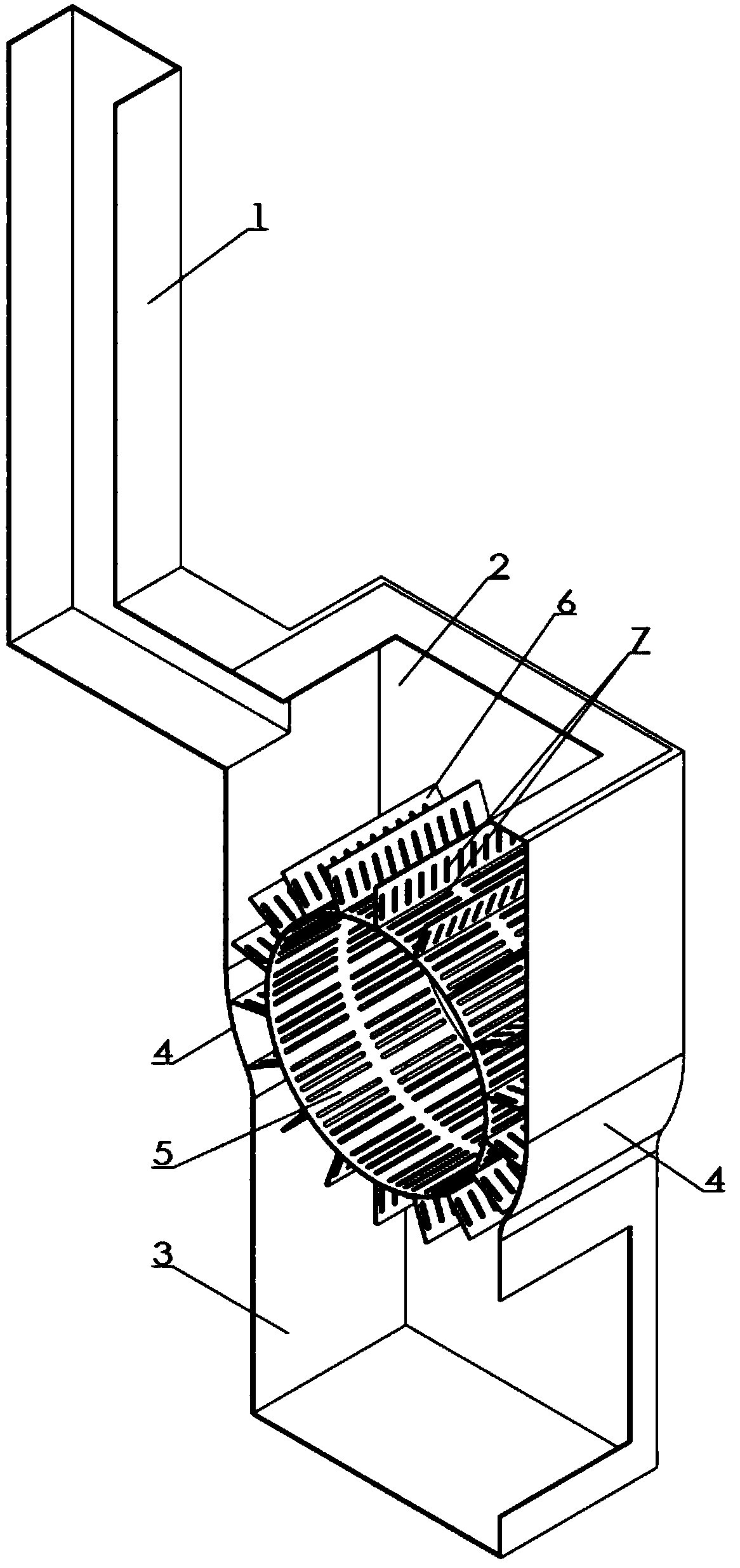
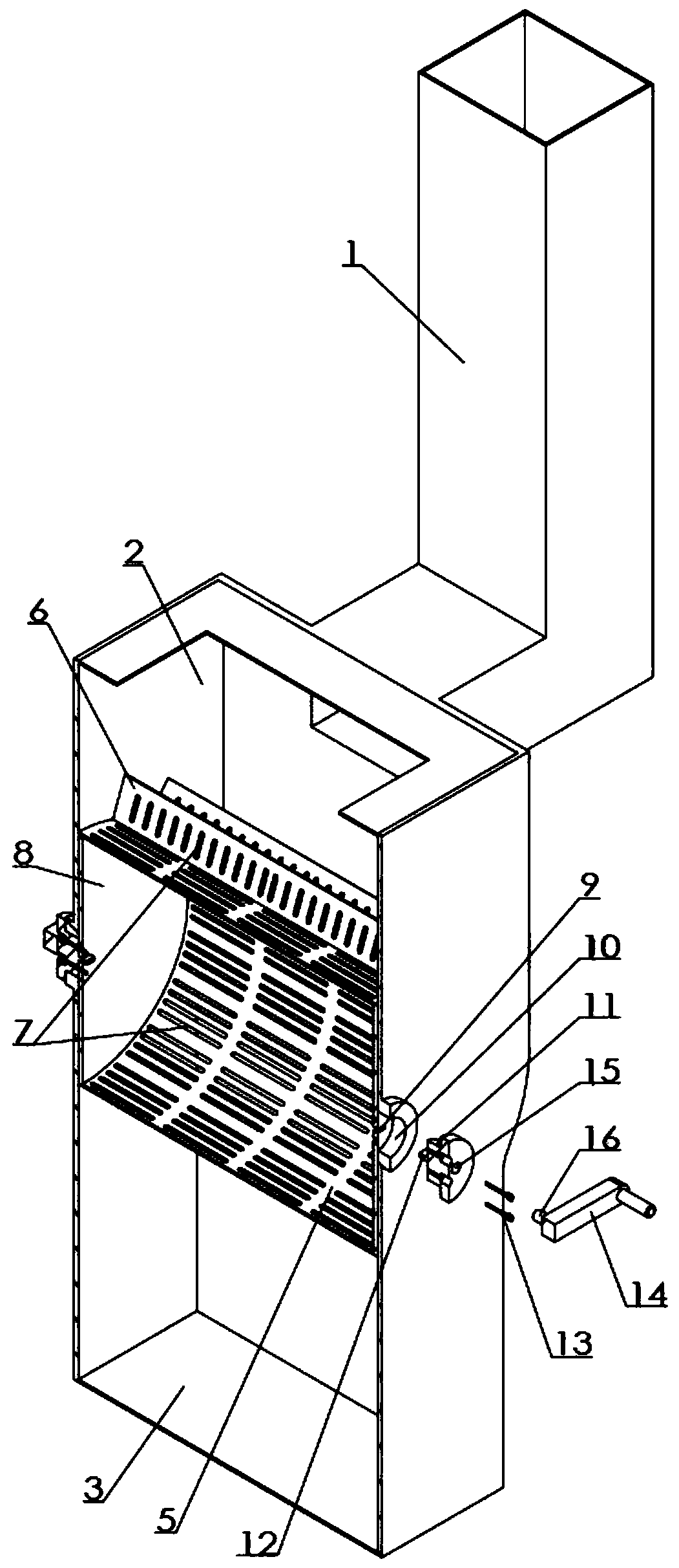
[0013] Examples of the present invention figure 1 , 2 As shown, the rotary biofuel combustion furnace is provided with a furnace chamber and a smoke exhaust pipe 1, the furnace chamber is provided with a combustion chamber 2 and an ash storage chamber 3, the ash storage chamber is located at the lower part of the combustion chamber, and the front and rear walls of the combustion chamber are respectively The arc-shaped transition plate 4 of the same size is transitionally connected with the front and rear walls of the ash storage chamber. A hollow drum 5 coaxial with the arc-shaped transition plate in the left and right directions of the axis is provided in the combustion chamber, and the outer wall of the drum is provided with circumferentially distributed The diaphragm 6 extending radially outward and parallel to the axis of the drum, the number of partitions facing the arc-shaped transition plate on one side of the drum at any angle is at least two, to avoid open air, and th...


PUM


Abstract

The invention discloses a rotary biofuel combustion furnace, which is characterized in that a hollow drum coaxial with an arc-shaped transition plate in the left and right directions of the axis is arranged in the combustion chamber, and radially outward The stretched partition is parallel to the axis of the drum. There is a gap between the outer edge of the partition and the arc-shaped transition plate. There are via holes on the drum and the partition. End plates are connected to both ends of the drum. Prismatic holes are provided at the axial center of the end plate. The left and right side walls of the combustion chamber are respectively provided with shaft holes coaxial with the end plate, and the shaft hole is fitted with a rotating body, and the end of the rotating body is provided with a prism matching the prism hole, and the rotating body and the end plate are connected as a whole by screws. There is a transmission hole at the end of the rotating body, and a transmission pin is arranged in cooperation with the transmission hole, and the transmission pin is connected with a rotating handle; the invention is fast and convenient for ash discharge, can effectively improve combustion efficiency, and makes people more willing to use biofuel particles, which is beneficial to energy consumption. save.

Description

technical field [0001] The invention relates to a heating appliance using biofuel particles, in particular to a rotary biofuel combustion furnace. Background technique [0002] With the vigorous development of the economy and the progress of social production, the excessive consumption of energy has caused huge damage to the environment on which human beings depend, and it is imminent to find new clean and renewable alternative energy sources. my country is a large agricultural country, and a large amount of straw is burned in the farmland every year. The heat energy of the straw cannot be fully utilized, mainly because the energy per unit volume of the straw is too low, resulting in burning and discarding. In order to make full use of the straw to solve the above problems, Our country vigorously advocates remaking straw into biofuel. Now it is mainly crushed and pressed into high-density particles to increase the heat energy per unit volume. The rear air flow is not smooth, ...

Claims


Application Information

Patent Timeline
Patent Type & Authority Patents(China)
IPC IPC(8): F24B1/08F24D15/02F23H9/02F23J1/06
CPCF23H9/02F23J1/06F24B1/08F24D15/02F23J2700/001
Inventor 杨世华
Owner CHONGQING HUAWANLUN BIOLOGICAL NEW ENERGY TECH CO LTD
Why Eureka
Try Eureka