
Multi-fuel heat conduction oil furnace

A heat-conducting oil furnace, multi-fuel technology, applied in the direction of fuel supply, combustion method, combustion equipment, etc., can solve the problems that the combustion chamber is not suitable for different types of fuels and moisture content, and the combustion space is small, so as to achieve low use cost and maintenance low volume effect

Active Publication Date: 2018-05-11
桂平南海科技有限公司
View PDF5 Cites 0 Cited by
  • Summary
  • Abstract
  • Description
  • Claims
  • Application Information

AI Technical Summary

Problems solved by technology

[0003] The existing heat-conducting oil furnace exists, the combustion space is small, and the combustion chamber is not separated from the main heat exchange chamber, causing the burned fly ash to wash the tube wall of the heat exchange tube in the main heat exchange chamber, and it must be repaired and replaced within 3 years Tubes, combustion chambers are not suitable for combustion of fuels of different types and moisture content

Method used


Image

  • Multi-fuel heat conduction oil furnace
  • Multi-fuel heat conduction oil furnace
  • Multi-fuel heat conduction oil furnace

Examples


Embodiment Construction

[0034] The present invention will be further described in detail below in conjunction with the accompanying drawings, so that those skilled in the art can implement it with reference to the description.

[0035] It should be noted that, in the description of the present invention, the terms "horizontal", "vertical", "upper", "lower", "front", "rear", "left", "right", "vertical", The orientation or positional relationship indicated by "horizontal", "top", "bottom", "inner", "outer", etc. is based on the orientation or positional relationship shown in the drawings, and is only for the convenience of describing the present invention and simplifying the description, and It is not to indicate or imply that the device or element referred to must have a particular orientation, be constructed in a particular orientation, or operate in a particular orientation, and thus should not be construed as limiting the invention.

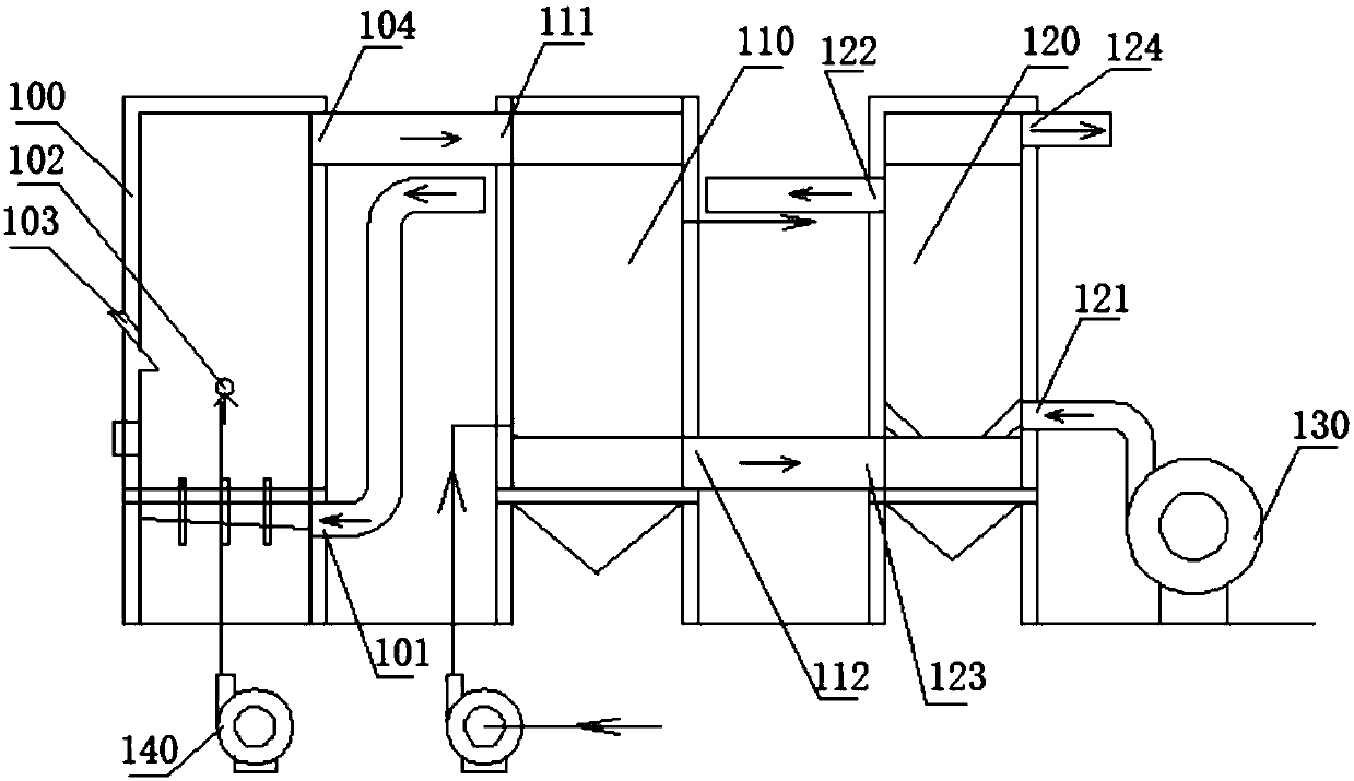
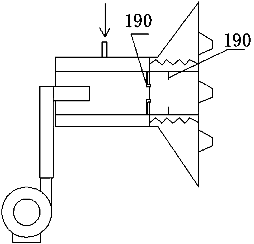
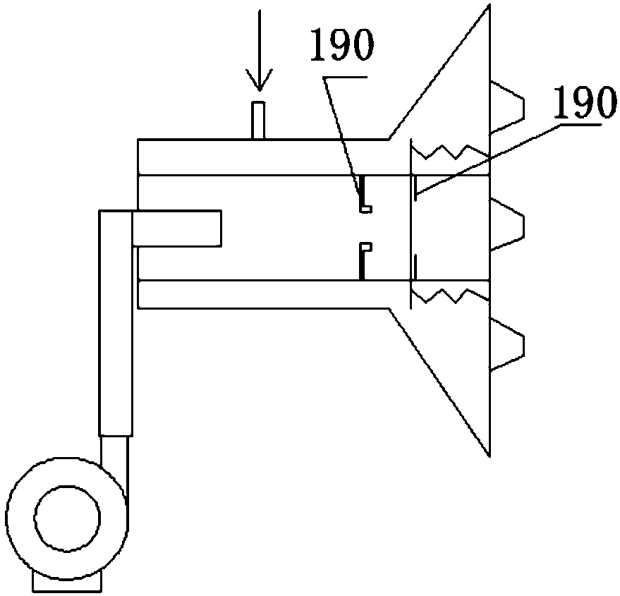
[0036] Such as Figure 1 to Figure 5 As shown, the present inve...


PUM


Abstract

The invention discloses a multi-fuel heat conduction oil furnace, and belongs to the technical field of the heat conduction oil furnaces. The multi-fuel heat conduction oil furnace comprises a combustion chamber, a main heat exchange chamber, an air heat exchange chamber, a primary fan and a secondary fan; a primary air opening, a secondary air opening, a fuel inlet and a high-temperature flue gasoutlet are formed in the side wall of the combustion chamber; the main heat exchange chamber is provided with a heat conduction oil inlet, a heat conduction oil outlet, a high-temperature flue gas inlet and a low-temperature flue gas outlet, and the high-temperature flue gas inlet communicates with the high-temperature flue gas outlet; the air heat exchange chamber is provided with a cold air inlet, a hot air outlet, a low-temperature flue gas inlet and a waste gas outlet, the hot air outlet communicates with the primary air opening, and the low-temperature flue gas inlet communicates with the low-temperature flue gas outlet; an air inducing pipe of the primary fan communicates with the cold air inlet; and an air inducing pipe of the secondary fan communicates with the secondary air opening. The combustion chamber is suitable for combustion of fuels with different types and different moisture content, so that the selection of the fuel is wider, the combustion chamber and the main heatexchange chamber are separated, so that the maintenance amount of the furnace is low, and the service life is longer.

Description

technical field [0001] The invention relates to a heat-conducting oil furnace. More specifically, the present invention relates to a multi-fuel thermal oil furnace. Background technique [0002] The heat-conducting oil furnace uses heat-conducting oil as the intermediate carrier to transmit heat energy. After the heat energy generated by burning fuel is exchanged in the heat-conducting oil furnace, the heat energy is transferred to the heat-conducting oil, so that the heat-conducting oil is heated to a certain temperature, and then circulated The oil pump sends it to the heat-using equipment, and the low-temperature heat-conducting oil after releasing heat energy is returned to the heat-conducting oil furnace to be reheated. This cycle can achieve the purpose of heat-transfer oil supplying heat to the outside. [0003] Existing heat-conducting oil furnaces exist, the combustion space is small, and the combustion chamber is not separated from the main heat exchange chamber, ...

Claims


Application Information

Patent Timeline
Patent Type & Authority Applications(China)
IPC IPC(8): F24H7/00F24H9/00F23K3/02F23J15/06
CPCF23J15/06F23K3/02F24H7/00F24H9/0084Y02E20/30
Inventor 骆湘平骆省安骆思嘉
Owner 桂平南海科技有限公司
Learn More