Orifice plate flow meter throttling device

A technology of orifice flowmeter and throttling device, which is applied in the direction of detecting fluid flow by measuring pressure difference, volume/mass flow generated by mechanical effects, etc., and can solve the problem of pipe pipe, liquid impact, and decrease in measurement accuracy of orifice flowmeter and other problems to achieve the effect of improving measurement accuracy and simple structure

Inactive Publication Date: 2017-03-22
付建军
View PDF0 Cites 1 Cited by
  • Summary
  • Abstract
  • Description
  • Claims
  • Application Information

AI Technical Summary

Problems solved by technology

In the prior art, since the central hole of the throttling piece is generally arranged in the center of the throttling piece, in this way, during the use of a fluid pipeline that is easy to precipitate liquid, the front end of the throttle piece is easy to accumulate eluate, which m

Method used


Image

  • Orifice plate flow meter throttling device

Examples


Embodiment 1

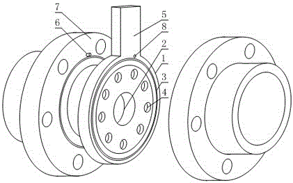
[0021] Such as figure 1 As shown, a throttling device for an orifice flowmeter includes two connecting flanges 7 arranged oppositely and an annular orifice plate body 1 arranged between the connecting flanges 7 , the orifice plate body 1 The center is also provided with a circular center hole 2, and also includes a permeable hole 4 arranged between the outer edge of the orifice plate body 1 and the center hole 2, the permeable hole 4 runs through both sides of the orifice plate body 1, and the orifice plate The outer edge of the body 1 is also fixedly connected with a strip-shaped installation handle 5, the length direction of the installation handle 5 is located in the radial direction of the orifice plate body 1, and the side of the orifice plate body 1 is also provided with a positioning hole 8 , at least one connecting flange 7 is provided with a positioning pin 6 matched with the positioning hole 8 .

[0022] In this embodiment, the orifice plate body 1 is used for clip-...

Embodiment 2

[0024] The present embodiment is further limited on the basis of embodiment 1, as figure 1 As shown, in order to facilitate the symmetry of the flow velocity of the gaseous fluid at each point on the pipeline cross-section relative to the centerline of the orifice plate body 1, and to facilitate the accuracy of the orifice flowmeter measurement, there are more than one permeable holes 4, and the permeable holes 4 are in the The orifice plate body 1 is evenly distributed in a ring shape relative to the centerline of the orifice plate body 1 .

[0025] In order to facilitate the static sealing effect between the orifice plate body 1 and the corresponding connecting flange, both sides of the orifice plate body 1 are provided with annular tenons and grooves 3 .

[0026] In order to weaken the impact of the friction between the impurity and the orifice plate body 1 on the shape of the central hole 2 and the permeable hole 4 when the gaseous fluid contains impurities, and to benefit...

Embodiment 3

[0029] This embodiment is further limited on the basis of any one of the technical solutions disclosed in any one of the above embodiments, such as figure 1 As shown, in order to facilitate the cooperation of the positioning hole 8 and the positioning pin 6 during the installation of the orifice plate body 1, the free end of the positioning pin 6 is also provided with a tapered guide tip. The reference point is a structural form for realizing the accurate positioning of the orifice plate body 1 and the connecting flange 7 , and there are two positioning pins 6 and two positioning holes 7 , and they are arranged in groups one by one. Wherein, setting one by one in groups means that one positioning pin 6 and one positioning hole 8 form one positioning point.


PUM


Abstract

The invention discloses an orifice plate flow meter throttling device which comprises two opposite connecting flanges, an annular orifice plate body and permeable holes, wherein the annular orifice plate body is arranged between the connecting flanges. A center hole is formed in the center of the orifice plate body, the permeable holes penetrate two sides of the orifice plate body, installing handles are fixedly connected at the outer edge of the orifice plate body, positioning pins are arranged on the connecting flanges, and positioning holes are formed in the orifice plate body. When the throttling device is used for the gas fluid pressure difference flow metering process during which liquid is easily precipitated, precipitated liquid cannot be gathered at the front end of the orifice plate body of a pipeline, measuring accuracy of an orifice plate type flow meter can be improved, installing requirements of a center hole axis on axes of the corresponding pipe sections are met, and the installing handles can serve as position calibrations of the permeable holes.

Description

technical field [0001] The invention relates to the field of fluid conveying pipe fittings, in particular to a throttling device for an orifice flowmeter. Background technique [0002] The orifice flowmeter is a non-scale flow measuring device. It is used in conjunction with a pneumatic or electric differential pressure transmitter or a double bellows differential pressure transmitter. Usually, the transmitter converts the differential pressure signal into a proportional output signal. , and then the measured flow is recorded, indicated or regulated by the secondary instrument or regulator. The principle of the orifice flowmeter is to install a throttling member such as an orifice plate or a nozzle inside the pipe. Since the diameter of the throttling member is smaller than the inner diameter of the pipe, when the fluid flows through the throttling member, the flow section suddenly shrinks and the flow speed increases. The static pressure of the fluid at the rear end of the...

Claims


Application Information

Patent Timeline
IPC IPC(8): G01F1/42
Inventor 付建军
Owner 付建军
Why Eureka
Try Eureka