A Non-contact Dynamic Measurement System of Rotary Shaft Torque Based on High Precision Key Phase

A dynamic measurement, high-precision technology, applied in torque measurement, measurement device, power measurement, etc., can solve the problem of unsuitable dynamic torque measurement of rotating shaft, and achieve the effect of eliminating accumulated errors, improving measurement accuracy, and reducing timing errors.

Active Publication Date: 2022-03-11
善测(天津)科技有限公司
View PDF14 Cites 0 Cited by
  • Summary
  • Abstract
  • Description
  • Claims
  • Application Information

AI Technical Summary

Problems solved by technology

[0008] The invention provides a non-contact dynamic measurement system of rotating shaft torque based on high-precision key phase. The invention solves the problem that the existing dynamic torque measurement of rotating shaft is not applicable in the actual field, and meets various needs in practical applications. , see the description below:

Method used


Image

  • A Non-contact Dynamic Measurement System of Rotary Shaft Torque Based on High Precision Key Phase
  • A Non-contact Dynamic Measurement System of Rotary Shaft Torque Based on High Precision Key Phase
  • A Non-contact Dynamic Measurement System of Rotary Shaft Torque Based on High Precision Key Phase

Examples


Embodiment 1

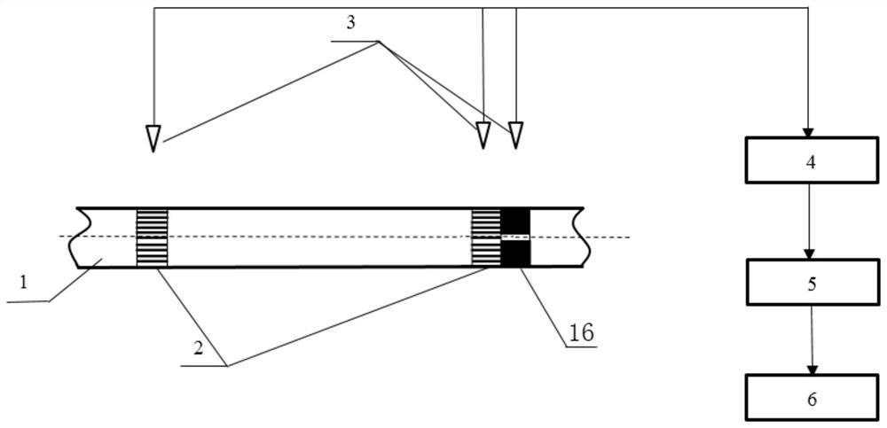
[0036] A non-contact dynamic measurement system for rotating shaft torque based on high-precision key phase, see figure 1 and figure 2 , the measuring system includes: a coding stripe 2 arranged on the measured rotating shaft 1,

[0037] Among them, a group of first coded stripes 2 are sprayed or pasted at a fixed distance on the tested rotating shaft 1, and the first coded stripes 2 are coded stripes with equal intervals between black and white (that is, there are two black and white alternated stripes on the tested rotating shaft 1). The first coding stripe 2); and spraying or pasting the second coding stripe 16 near any one of the first coding stripe 2, the second coding stripe 16 has only one white stripe (that is, the white stripe is positioned at the first black and white stripe Near the coding stripe 2, and there is only one white stripe), the white stripe of the second coding stripe 16 is used as a key phase signal.

[0038] Facing each coded stripe (i.e. a group of...

Embodiment 2

[0045] Combine below Figure 1 to Figure 4 The scheme in Example 1 is discussed in detail, see the following description for details:

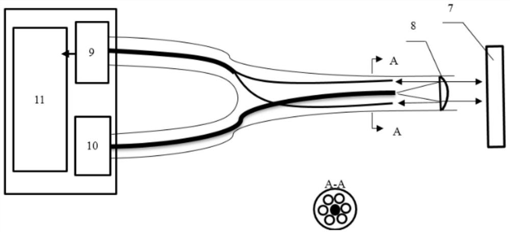
[0046] The embodiment of the present invention adopts fiber optic timing sensor 3, see figure 2 , has the advantages of lightness, softness, and good electromagnetic compatibility, and is suitable for on-site applications. Some on-site environments require a large working distance of the probe (that is, the distance from the end face of the probe to the axis) for safety reasons, and a focusing and collimating structure is designed.

[0047]The fiber optic timing sensor 3 adopts Y-shaped fiber bundle, and the central fiber is the transmitting fiber, which closely surrounds M receiving fibers, which can be precisely circled 1 or 2 times. Generally, M=6 is sufficient to meet the requirements.

[0048] The laser light source 10 transmits and emits the laser light through the emitting fiber, and collimates and emits the laser light through the f...


PUM


Abstract

The invention discloses a non-contact dynamic measurement system for torque of a rotating shaft based on a high-precision key phase, which includes: spraying or pasting a group of first coding stripes at a fixed distance on the rotating shaft to be measured, which are black and white coding stripes at equal intervals; And spray or paste the second code stripe near any one of the first code stripes, which has only one white stripe, and the second code stripe is used as a key phase signal; facing each code stripe, install a fiber-optic timing sensor respectively , the probe of each sensor is equipped with a focusing lens to collimate the outgoing light, and the beam diameter is small; the fiber-optic timing sensor corresponding to the second code stripe is used as a synchronous key phase; the fiber-optic timing sensor receives the reflected light signal of the white stripe , the reflected light signal is converted into a timing pulse through a signal processing circuit, and then processed through a high-speed and high-precision timing acquisition card input controller. The invention solves the problem that the existing dynamic torque measurement of the rotating shaft is not applicable in the actual field.

Description

technical field [0001] The invention relates to the field of dynamic torque measurement of rotating shafts, in particular to a non-contact dynamic measuring system of rotating shaft torque based on high-precision key phase. Background technique [0002] At present, the shaft dynamic torque measurement mainly has the following types: [0003] (1) Resistance strain gauge torque measurement: Paste the strain gauge on the measured shaft system, connect it to an external circuit through a lead, and obtain the torque information of the shaft system by measuring the resistance change of the resistance strain gauge. This measurement is a contact measurement. There are shortcomings such as complicated test and modification, difficult signal transmission of rotating parts, and low reliability, making it difficult to achieve high-speed dynamic torque measurement. [0004] (2) Laser Doppler torque measurement: use the laser sensor to measure the rotational speed of the measured shaft a...

Claims


Application Information

Patent Timeline
Patent Type & Authority Patents(China)
IPC IPC(8): G01L3/00
CPCG01L3/00
Inventor 叶德超李杨宗段发阶苏宇浩李旭郭岩
Owner 善测(天津)科技有限公司
Why Eureka
Try Eureka