Sampling method and sampling device for original state sandy soil
A sampling device and sandy soil technology, applied in the field of geotechnical exploration engineering, can solve the problems of soil sample disturbance, low cohesion, and inability to represent the original soil characteristics, and achieve the effect of maintaining the original state and not being easily disturbed
- Summary
- Abstract
- Description
- Claims
- Application Information
AI Technical Summary
Problems solved by technology
Method used
Image
Examples
Embodiment 1
[0045] A method for sampling undisturbed sandy soil, comprising the following steps:
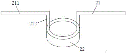
[0046] (1) Assemble the force applicator 2, the sampling sleeve 3, and the soil-taking edge 4 together. In this embodiment, the force applicator 2, the sampling sleeve 3, and the soil-taking edge 4 are detachably clamped ;
[0047] (2) For the sandy soil to be sampled, use a shovel to clean up the soil layer above it. The cleaning area should be larger than the area to be sampled. The soil layer above the sandy soil varies according to the geology;
[0048] (3) Freeze the sandy soil area to be sampled. After the sandy soil is frozen, the sandy soil in the area will be solidified together to achieve the function of "shaping", so that in the subsequent sampling process It can avoid the deformation of sandy soil due to disturbance, and can well maintain the original state of the soil sample;
[0049] (4) After the freezing starts, pay attention to protecting the surrounding soil in the area to ...
Embodiment 2
[0073] Such as Figure 8-10 As shown, the difference between this embodiment and Embodiment 1 is that the lower end of the force applicator 2 is detachably clamped with the upper end of the sampling sleeve 3, and the lower end of the sampling sleeve 3 is connected with the cutting edge of the soil. The upper end of 4 is detachably clamped;
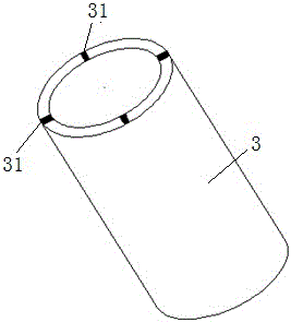
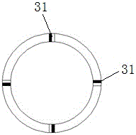
[0074] Specifically, the inner walls of the upper and lower ends of the sampling sleeve 3 are provided with bayonet openings 31 at intervals in the circumferential direction, and the outer walls of the lower end of the force applicator 2 and the upper end of the cutting edge 4 are respectively provided with The block 7 matched with the bayonet socket 31, the inner wall of the upper end and the lower end of the sampling sleeve 2 respectively have a step structure 8 at the inner end of the bayonet socket 31, the thickness of the step structure 8 and the force applicator 2, soil extraction The thickness of the inserting portion of the cuttin...
Embodiment 3
[0077] The difference between the present embodiment and the second embodiment is that the lower end of the force applicator 2 is threadedly connected to the upper end of the sampling sleeve 3, and the lower end of the sampling sleeve 3 is threadedly connected to the upper end of the cutting edge 4;
[0078] Specifically, the inner walls of the upper and lower ends of the sampling sleeve 3 are provided with internal threads, and the outer walls of the lower end of the force applicator 2 and the upper end of the cutting edge 4 are respectively provided with threads that cooperate with the internal threads. The outer thread of the upper end and the lower end of the sampling sleeve 3 has a step structure on the inner end of the inner thread respectively, and the thickness of the step structure is the same as that of the force applicator 2 and the insertion part of the soil cutting edge 4, So that the internal diameters of the force applicator 2, the sampling sleeve 3 and the soil-...
PUM
 Abstract
Description
Claims
Application Information
 - R&D
- Intellectual Property
- Life Sciences
- Materials
- Tech Scout
- Unparalleled Data Quality
- Higher Quality Content
- 60% Fewer Hallucinations
Browse by: Latest US Patents, China's latest patents, Technical Efficacy Thesaurus, Application Domain, Technology Topic, Popular Technical Reports.
© 2025 PatSnap. All rights reserved.Legal|Privacy policy|Modern Slavery Act Transparency Statement|Sitemap|About US| Contact US: help@patsnap.com


