
An optical fiber docking device

A docking device and optical fiber technology, applied in the field of optical fiber communication, can solve the problems of time-consuming and huge workload, and achieve the effects of simple operation, reduced horizontal occupation area, and reduced manual participation.

Active Publication Date: 2018-08-28
NINGBO YINGMING ELECTRIC TECH
View PDF5 Cites 0 Cited by
  • Summary
  • Abstract
  • Description
  • Claims
  • Application Information

AI Technical Summary

Problems solved by technology

However, due to many factors such as geographical dispersion and cumbersome manual switching operations, such manual operations in daily life have a huge and time-consuming workload. Therefore, how to realize the automatic docking and exchange of optical fiber cores has become a great concern to people. question

Method used


Image

  • An optical fiber docking device
  • An optical fiber docking device
  • An optical fiber docking device

Examples


Embodiment Construction

[0043] As mentioned in the background section, how to realize the automatic docking and exchange of optical fiber cores has become a problem of great concern to people.

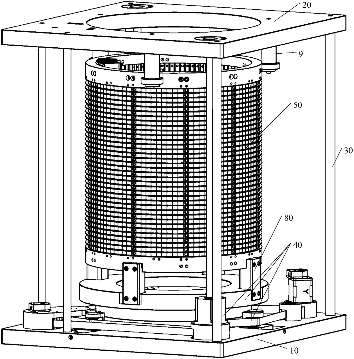
[0044] In view of this, an embodiment of the present invention provides an optical fiber docking device, including:

[0045] The base and the cover plate are oppositely arranged, and the support rod is arranged between the base and the cover plate;

[0046] a first power structure arranged on the base;

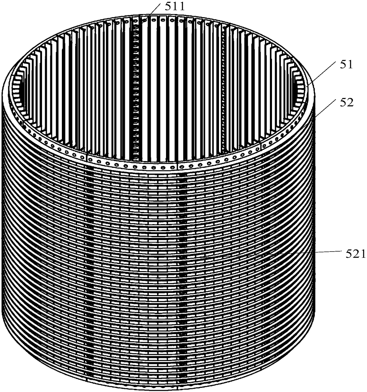
[0047] A docking matrix bucket fixedly connected to the first power structure, the docking matrix bucket is a hollow columnar structure, driven by the first power structure to rotate along a preset direction, and the docking matrix bucket is provided with multiple a butt holes arranged in a matrix along the first direction and the second direction;

[0048] a second power structure fixedly connected to the base;

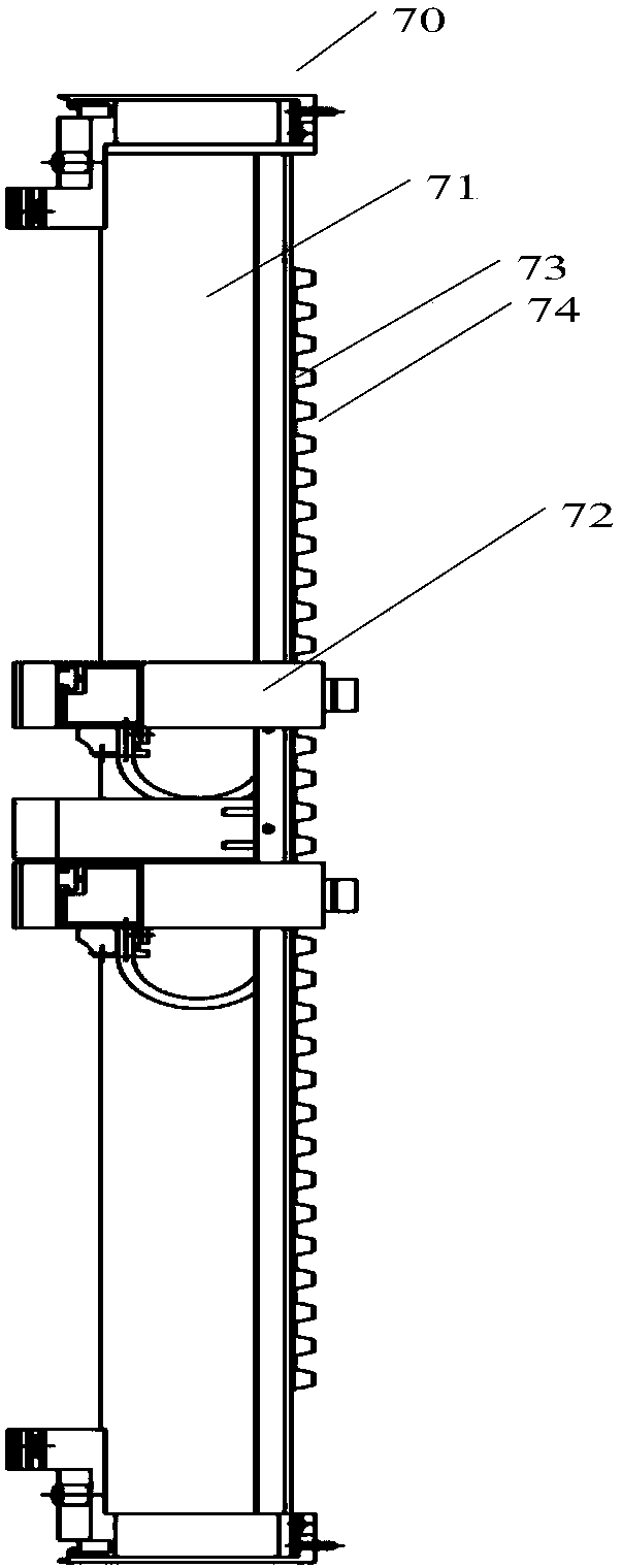
[0049] Located in the cavity of the docking matrix bucket, a plurality of line docking device...


PUM


Abstract

The embodiment of the invention discloses an optical fiber butting device, including a butting matrix barrel and a plurality of line butting devices located in a butting matrix barrel cavity and fixedly connected with the butting matrix barrel, one line butting device is fixes an external optical fiber, during specific working, only the line butting devices need to be utilized to fix external optical fibers, the external optical fibers are inserted in butting holes of the butting matrix barrel, then the tail fibers or two cord circuit butting pieces connected by the tail fibers are utilized to be inserted in the butting holes into which two external optical fibers to be butted are inserted, thus automatic butting of the two external optical fibers can be realized, the operation is simple, manual participation can be greatly reduced, and plenty of manpower and material resources are saved. In addition, in the optical fiber butting device provided by the embodiment of the invention, the butting matrix barrel is of a hollow columnar structure, and the butting holes are arranged on the side wall of the butting matrix barrel, and thus on the premise of the same number of butting holes, the horizontal occupation area of an optical fiber core butting matrix structure is greatly reduced.

Description

technical field [0001] The invention relates to the technical field of optical fiber communication, in particular to an optical fiber docking device. Background technique [0002] With the rapid development of power grid construction and the continuous improvement of the automation of power system equipment, the optical fiber power communication network has also achieved unprecedented development. [0003] At present, as the basic bearer network of optical fiber communication transmission - optical fiber network, its operation and maintenance work is still in the original manual mode, that is, it usually needs to manually go to the site to perform fiber jumping operations to realize the docking exchange between different optical fibers. However, due to many factors such as geographical dispersion and cumbersome manual switching operations, such manual operations in daily life have a huge and time-consuming workload. Therefore, how to realize the automatic docking and exchang...

Claims


Application Information

Patent Timeline
Patent Type & Authority Patents(China)
IPC IPC(8): G02B6/38
CPCG02B6/3807
Inventor 张莉
Owner NINGBO YINGMING ELECTRIC TECH
Learn More