Cabinet equipment label

A label and device technology, applied in the computer field, can solve the problems of unusable information labeling, the influence of user visual reading label information, and the influence of users on the operation of the device panel, so as to achieve the effect of not affecting the heat dissipation of the device and enriching the label function.

Inactive Publication Date: 2017-03-22
BEIJING TEAMSUN TECH
View PDF13 Cites 4 Cited by
  • Summary
  • Abstract
  • Description
  • Claims
  • Application Information

AI Technical Summary

Problems solved by technology

Due to the huge amount of equipment in the cabinet, self-adhesive labels and paper labels are pasted on the equipment panels. If the labels are large, it will affect the user's operation on the equipment panels. If the labels are small, it will not be possible to label the equipment information. Useful information is marked out, and due to the limitation of the marked area, it also affects the user's visual reading of the label information, and also has a great impact on the heat dissipation of the equipment in the cabinet

Method used


Image

  • Cabinet equipment label
  • Cabinet equipment label
  • Cabinet equipment label

Examples


Embodiment 1

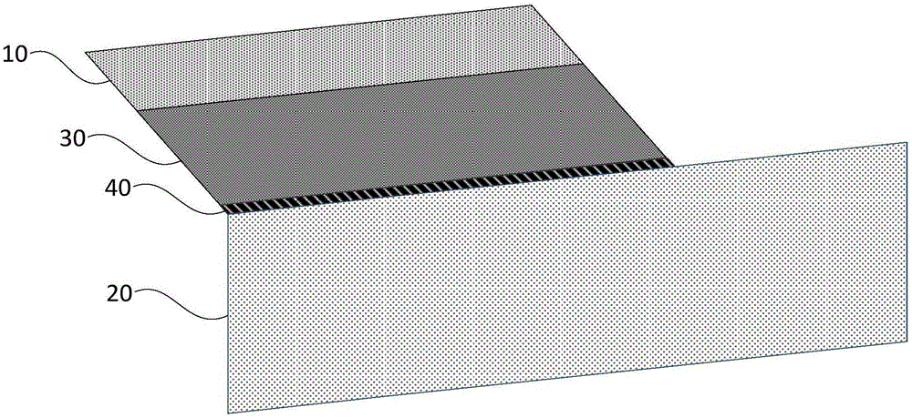
[0023] figure 1 It is a schematic structural diagram of the cabinet equipment label provided by Embodiment 1 of the invention, and this embodiment is applicable to equipment labeling. The cabinet device label can be implemented in a hardware manner.

[0024] The rack equipment label specifically includes: a sticking area 10 , a label function area 20 and a supporting area 30 .

[0025] Among them, the sticking area 10 is used to paste the label and the equipment; the label functional area 20 is used for displaying label information; the support area 30 is rigidly connected with the sticking area 10, and is connected to the label functional area 30 through a hinge 40 connections for providing support for the label functional area 30 and extending the label functional area 30 to a set distance from the equipment to be marked.

[0026] Specifically, the sticking area 10 is used to fix the label of the cabinet equipment on the equipment, and its sticking position can include the...

Embodiment 2

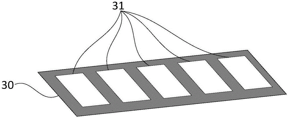
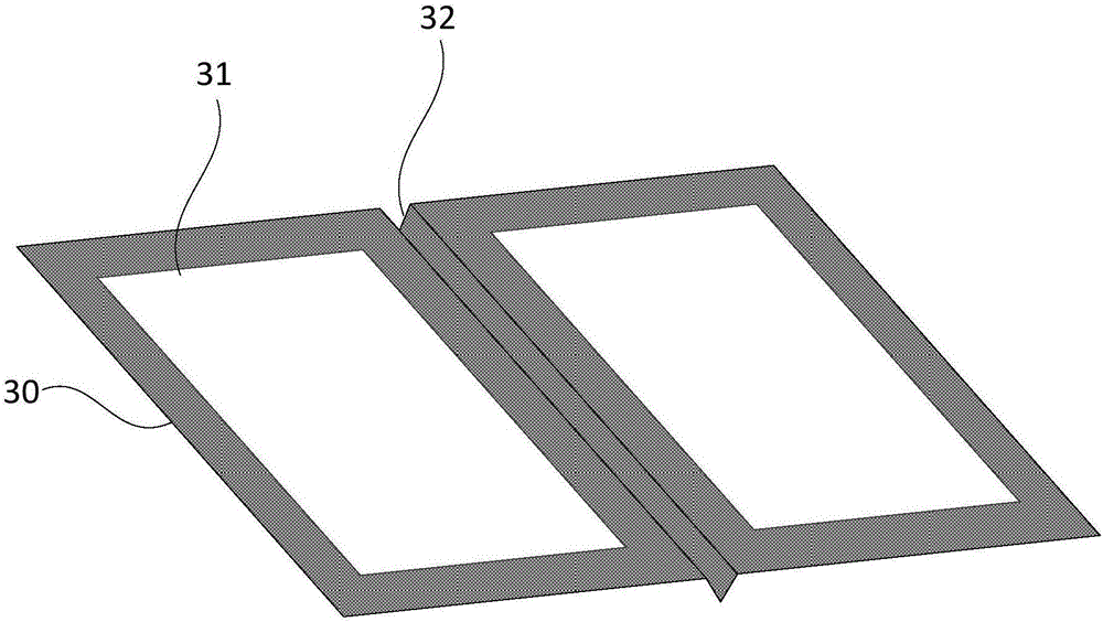
[0033] Figure 2a and Figure 2b It is a schematic structural diagram of the rack equipment label support area provided by the second embodiment of the invention. On the basis of the above embodiments, this embodiment provides a preferred example of the rack equipment label.

[0034] Preferably, the supporting area 30 has ventilation holes 31 .

[0035] Such as Figure 2a As shown, the ventilation hole 31 can be arranged in a rectangle and other shapes. Setting the ventilation holes 31 in the supporting area 30 not only saves materials and reduces the manufacturing cost, but also provides conditions for ventilation and heat dissipation of the equipment, and does not affect the heat dissipation of the equipment while sticking the labels of the equipment. Avoid equipment failure due to large heat generation and poor heat dissipation.

[0036] Preferably, the supporting area 30 is provided with a reinforcing supporting structure 32 .

[0037] Such as Figure 2b As shown, th...

Embodiment 3

[0041] image 3 It is a schematic structural diagram of the rack equipment label provided by Embodiment 3 of the invention. On the basis of the above embodiments, this embodiment provides a preferred example of the rack equipment label.

[0042] The label functional area 20 includes a temperature indicating area 21 , a visual label area 22 and an RFID label area 23 .

[0043] Preferably, the temperature indication area 21 is provided with a liquid crystal color-changing thermometer 211 to detect the ambient temperature around the panel of the device to be marked. The liquid crystal color-changing thermometer 211 is set because the liquid crystal color-changing thermometer marks the current temperature by color, the reading is obvious, intuitive and convenient, and it can be bent arbitrarily and is not easy to break, avoiding the harm of glass breakage and mercury poisoning caused by traditional thermometers. It is safe, The advantages of environmental protection, science and ...


PUM


Abstract

The invention discloses a cabinet equipment label. The cabinet equipment label comprises a sticking area which is used for sticking a label body to equipment, a label function area used for displaying label information; and a supporting area rigidly connected with the sticking area and connected with the label function area through a hinge piece, and the supporting area is used for providing supporting force for the label function area and extending the label function area to the position away from the equipment to be marked by a set distance. The cabinet equipment label has the beneficial effects that heat dissipation of the equipment is not affected, sufficient marking space can be provided, and richer label functions can be provided.

Description

technical field [0001] The embodiment of the present invention relates to the technical field of computers, in particular to a cabinet equipment label. Background technique [0002] At this stage, the rapid development of the computer field has become a necessity for people to work, study and live. [0003] In large and medium-sized computer rooms, in order to identify the equipment in the cabinet, information labels are usually attached to the equipment. Common labels are self-adhesive labels or paper labels applied by users themselves. Due to the huge amount of equipment in the cabinet, self-adhesive labels and paper labels are pasted on the equipment panels. If the labels are large, it will affect the user's operation on the equipment panels. If the labels are small, it will not be possible to label the equipment information. Useful information is marked out, and due to the limitation of the marked area, it also affects the user's visual reading of the label information,...

Claims


Application Information

Patent Timeline
Patent Type & Authority Applications(China)
IPC IPC(8): G09F3/02G09F3/10
CPCG09F3/0288G09F3/0297G09F3/10
Inventor 汪大海
Owner BEIJING TEAMSUN TECH
Why Eureka
Try Eureka