Manufacturing method of metal runners used for liquid cooling and liquid cooling metal runner cold plate

A technology of metal runners and manufacturing methods, which is applied in the direction of cooling/ventilation/heating transformation, electrical components, electrical equipment structural parts, etc., and can solve the problems of cold plate reliability and heat dissipation effect reduction, blocked flow passages, unreliable welding, etc. Problems, to achieve the effect of simple processing, avoid welding problems, and high reliability

Active Publication Date: 2016-06-01
CHINA ELECTRONICS TECH GRP NO 26 RES INST
View PDF5 Cites 7 Cited by
  • Summary
  • Abstract
  • Description
  • Claims
  • Application Information

AI Technical Summary

Problems solved by technology

This method is simple and practical, but because the solder flowing during the welding process is easy to overflow into the flow channel along the metal surface to block the flow channel, and due to the loss of solder, the welding between the ribs of the two metal substrates will be unstable, which will lead to Reduced reliability and cooling effect of the cold plate
[0007] To sum up, there are deficiencies in varying degrees in the existing manufacturing methods of metal runners for liquid cooling.

Method used


Image

  • Manufacturing method of metal runners used for liquid cooling and liquid cooling metal runner cold plate
  • Manufacturing method of metal runners used for liquid cooling and liquid cooling metal runner cold plate
  • Manufacturing method of metal runners used for liquid cooling and liquid cooling metal runner cold plate

Examples


Embodiment 1

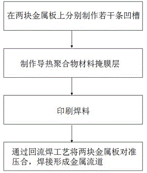
[0037] Such as figure 1 As shown, the method for manufacturing a metal runner for liquid cooling in the present invention comprises the following steps:

[0038] 1) Make several grooves on two metal plates;

[0039] This step can be realized by the following method.

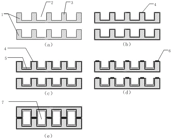
[0040] 1.1) Grooves 2 are made on two metal plates 1 by milling process or laser process ( figure 2 shown as four), and form (five) ribs 3, as figure 2 (a) shown. Wherein, the processing material of the metal plate 1 is 5A06 antirust aluminum, the depth of the groove 2 is about 2-10 mm, the width is about 5-8 mm, and the width of the rib 3 is about 2-5 mm.

[0041] 1.2) Pretreatment before electroplating: degrease in an alkaline degreasing solution at a temperature of 60°C-80°C, then soak in a rust remover for 15-30 minutes at a temperature of 15°C-35°C, and then use pure distilled water Rinse under high pressure for 8-12 minutes until the monitored pH of the effluent distilled water is 6-8.

[0042] 1.3)...

Embodiment 2

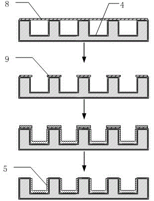
[0052] Embodiment 2 is basically the same as Embodiment 1, including four major steps, the difference lies in the method of making a thermally conductive polymer material mask layer in step 2).

[0053] In step 2) of Example 2, first paste the dry film 8 on the groove surface of the metal plate as a whole, and then make the dry film pattern 9 through exposure and development, that is, only leave the dry film on the ribs, and then spray thermally conductive polymerization on the concave surface as a whole Finally remove the dry film on the ribs and the thermally conductive polymer material on the dry film, leaving only the inside of the groove and forming a thermally conductive polymer material mask layer 5, such as image 3 shown. After the thermally conductive polymer material mask layer is fabricated, solder printing is performed on the ribs and metal runners are formed by welding.

[0054] The liquid-cooled metal runner cold plate includes two metal plates with the same st...


PUM

PropertyMeasurementUnit
thicknessaaaaaaaaaa
thicknessaaaaaaaaaa
thicknessaaaaaaaaaa

Abstract

The invention discloses a manufacturing method of metal runners used for liquid cooling and a liquid cooling metal runner cold plate. The manufacturing steps are listed as follows: 1) multiple grooves of the same structure are respectively manufactured on two metal plates and rib strips of which the number is more than one of the number of the grooves are formed, and a metal weldable layer is manufactured on the upper surface of the rib strips and the bottom part and the side wall of the grooves; 2) a heat-conducting polymer material mask layer is manufactured on the metal weldable layer of the bottom part and the side wall of the grooves; 3) a welding flux layer is manufactured on the upper surface of the rib strips; and 4) the two metal plates are buckled together and the grooves and the rib strips arranged on the two metal plates are corresponding in a one-to-one way, and the welding flux layers of the rib strips of the two metal plates are correspondingly welded through a reflow welding technology so that the metal runners are formed. The manufacturing method is simple in manufacturing, and the manufactured runners are high in reliability and great in heat radiation.

Description

technical field [0001] The invention relates to the technical field of heat dissipation of high heat flux density electronic devices, in particular to a method for manufacturing a liquid-cooled metal flow channel and a liquid-cooled metal flow channel cold plate. Background technique [0002] All kinds of electronic components have been developing towards the trend of continuous reduction in size and continuous improvement in performance. In the 1980s, the heat flux density of electronic components was about 10W / cm2, but it has exceeded 250W / cm2 at present, and this development trend is constantly expanding. According to statistics from the U.S. Naval Research Institute, the heat flux density of T / R components for radar may exceed 1000W / cm2. If the heat generated by the electronic components inside the T / R component cannot be effectively dissipated, the operating temperature will rise sharply. high, eventually leading to device failure. [0003] In order to solve the heat ...

Claims


Application Information

Patent Timeline
Patent Type & Authority Applications(China)
IPC IPC(8): H05K7/20
CPCH05K7/20254
Inventor 余怀强桂进乐王腾邓立科蒋创新汤劲松
Owner CHINA ELECTRONICS TECH GRP NO 26 RES INST
Why Eureka
Try Eureka