Spatial calibration method of stereo system and mobile terminal device thereof

A sound system and space calibration technology, applied in electrical components and other directions, can solve the problems of poor adaptability, unable to meet the restoration of sound authenticity, unable to meet the optimal listening point position of static fixed sound system, etc., to achieve the effect of improving sound authenticity

Active Publication Date: 2017-03-22
SHENZHEN IMKS TECH
View PDF3 Cites 9 Cited by
  • Summary
  • Abstract
  • Description
  • Claims
  • Application Information

AI Technical Summary

Problems solved by technology

[0002] The current audio system is designed for a relatively preset fixed position, but in fact, people generally cannot satisfy the requirement of being fixed at the best listening point of the audio system when enjoying music in daily life, and even many audio systems are not at all without accurate and efficient spatial calibration
In the prior art, the corresponding compensation is basically done by manually setting the distance of the speakers of each channel. However, due to the transmission characteristics of the sound radiated by the speakers, in order to achieve the best auditory experience, the placement of the speakers and the listening position point In fact, there are very strict requirements, such as: the listening position point must be located at a relatively fixed position on the symmetry line, then, for music appreciation in ordinary environments such as family and public, it seems dull and poor in adaptability; and, because The spread of sound and the directional characteristics of the speaker system, when the sound arrives at different listening positions, the loudness of different frequencies, the phase and time between different channels have actually changed, which cannot satisfy the authenticity of the sound.

Method used


Image

  • Spatial calibration method of stereo system and mobile terminal device thereof
  • Spatial calibration method of stereo system and mobile terminal device thereof
  • Spatial calibration method of stereo system and mobile terminal device thereof

Examples


Embodiment Construction

[0036] The preferred embodiments of the present invention will be further described in detail below in conjunction with the accompanying drawings.

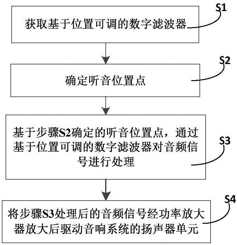
[0037] like figure 1 As shown, this example provides a spatial calibration method for a stereo system, including the following steps:

[0038] Step S1, obtaining a position-based adjustable digital filter;

[0039] Step S2, determining the listening position point;

[0040] Step S3, based on the listening position determined in step S2, the audio signal is processed through a position-adjustable digital filter;

[0041] In step S4, the audio signal processed in step S3 is amplified by the power amplifier to drive the speaker unit of the audio system.

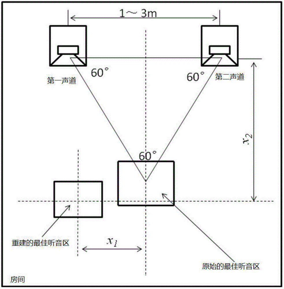
[0042]In order to facilitate the description of its working principle, the spatial calibration method of the stereo sound system described in this example takes a two-channel stereo sound system as an example. It is worth mentioning that the spatial calibration method described i...


PUM


Abstract

The invention provides a spatial calibration method of a stereo system and a mobile terminal device thereof. The spatial calibration method comprises the following steps: step S1, obtaining a digital filter based on an adjustable position; step S2, determining a listening position point; step S3, processing an audio signal through the digital filter based on the adjustable position based on the listening position point determined in step S2; and step S4, amplifying the audio signal processed in step S3, and driving a loudspeaker unit of the stereo system. According to the spatial calibration method provided by the invention, balance processing and delay processing are performed on the audio signal based on the listening position point selected by a user, the delay processing and the balance processing are performed on the sound radiation characteristics, the sound directivity and the spatial structure acoustic characteristics of the stereo system for different listening position points in a listening room so as to realize targeted calibration and optimization, and the validity of voice at different listening position points is maximally improved.

Description

technical field [0001] The invention relates to a sound calibration method, in particular to a space calibration method for a stereo sound system, and to a mobile terminal device using the space calibration method for the sound system. Background technique [0002] The current audio system is designed for a relatively preset fixed position, but in fact, people generally cannot satisfy the requirement of being fixed at the best listening point of the audio system when enjoying music on a daily basis. There is no accurate and effective spatial calibration function. In the prior art, the corresponding compensation is basically done by manually setting the distance of the speakers of each channel. However, due to the transmission characteristics of the sound radiated by the speakers, in order to achieve the best auditory experience, the placement of the speakers and the listening position point In fact, there are very strict requirements, such as: the listening position point m...

Claims


Application Information

Patent Timeline
Patent Type & Authority Applications(China)
IPC IPC(8): H04R29/00
CPCH04R29/001
Inventor 谢诗文
Owner SHENZHEN IMKS TECH
Why Eureka
Try Eureka