Valve for tubeless tires

A technology for tires and inner tubes, applied in tire inflation valves, tire parts, transportation and packaging, etc., can solve problems such as unclear sealants, and achieve the effect of compact design

Active Publication Date: 2017-03-22
SPORT COMPONENTS
View PDF13 Cites 2 Cited by
  • Summary
  • Abstract
  • Description
  • Claims
  • Application Information

AI Technical Summary

Problems solved by technology

However, it is still not clear how exactly the amount of sealant in a pneumatic tire can be determined and / or adjusted

Method used


Image

  • Valve for tubeless tires
  • Valve for tubeless tires
  • Valve for tubeless tires

Examples


Embodiment Construction

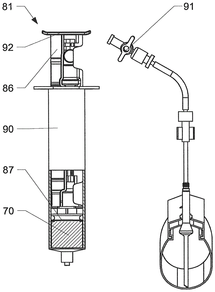
[0094] figure 1 An embodiment of a valve stem system 1 is shown mounted on a wheel rim 50 (in particular a tubeless wheel) comprising a mounted tire 60 . The tire 60 is filled with a sealant 70 to seal the tire. The stem system 1 protrudes towards the outer (central) surface of the rim and is fastened at the rim 50 using nuts 14 .

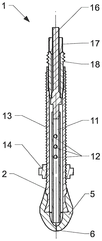
[0095] figure 2 An embodiment of a valve stem system 1 comprising a tubular valve stem body 2 and a first valve element 5 is shown. The valve stem body 2 has a first end 3 and a second end 4 connected by a passage extending through the valve body 2 in the longitudinal direction. A cap 15 is provided which is screwable at the first end 3 of the valve stem body 2 . The cover 15 protects the inner volume of the valve stem body 2 from contamination and may act as an additional sealing element to prevent the passage of pressurized gas through the valve stem body 2 . The first valve element 5 is arranged at the second end 4 of the valve stem body 2...


PUM


Abstract

The invention is directed to a valve stem system (1) for tubeless wheels. The valve stem system (1) comprises a valve stem body (2) with a first end (3) and a second end (4), wherein the second end (4) is located in a tire / rim-volume when mounted at the wheel. A first valve element (5) is arranged at the second end (4) of the valve stem body (2). The first valve element (5) is a self-sealing one-way valve. The invention further concerns a probe (30) for a valve stem system, a method to test the amount of sealant in a wheel and a refilling assembly (80) for the wheel.

Description

[0001] field of invention [0002] The invention relates to a valve stem system for eg a bicycle wheel, in particular for a tubeless wheel. Background technique [0003] WO 2010 / 009887 relates to a device for filling pneumatic tires, especially bicycle tyres, using tire sealing fluid through a valve of the tire. The device is configured as an adapter set with a connector for the tire fluid and with individual parts that can be plugged into each other and by plugging, clamping and / or Screwed into the valve, the individual components may vary relative to each other depending on the valve type, such as a Dunlop valve, Quick valve, or Sclaverand valve. [0004] US 2006 / 0021472 relates to a device for injecting tire sealant fluid into a tyre. A syringe type reservoir is connected to a long flexible tube which in turn is connected to a valve stem connector. The stem connector has two different threads (Schrader and Presta) to accommodate both types of valve stems. Schrader threa...

Claims


Application Information

Patent Timeline
Patent Type & Authority Applications(China)
IPC IPC(8): B60C29/00B60C29/06
CPCB60C29/002B60C29/005B60C29/062F16K15/147F16K15/202G01N33/26B60C5/004B60C5/12B60C25/005B60C25/0551B60C25/0554B60C2200/12
Inventor P.科布勒D.伊格特
Owner SPORT COMPONENTS
Why Eureka
Try Eureka