Method and system for removing carbon dioxide

a carbon dioxide and carbon dioxide technology, applied in the direction of sustainable manufacturing/processing, separation processes, well accessories, etc., can solve the problems of small fraction of cbm economically recoverable, and the limitation of depressurization to coal beds with higher permeability

Pending Publication Date: 2021-10-28
EZ ENERGIES GMBH
View PDF0 Cites 0 Cited by
  • Summary
  • Abstract
  • Description
  • Claims
  • Application Information

AI Technical Summary

Benefits of technology

[0017]Depending on the amount of biomass processed to biogas, the method allows removing high amount of CO2 from the atmosphere or the ocean. Depending on the source of biomass, for example biomass of plants grown in the atmosphere, or for example biomass of phytoplankton grown in the ocean, the method allows removing CO2 from the atmosphere or the ocean.
[0018]Biogas is derived from organic material, the biomass. Usually biogas is harvested by processing biomass in such a way that encourages microorganisms to digest the organic material in a process that produces gas as a result. This process is known as anaerobic digestion. The anaerobic digestion process occurs naturally with waste comprising biomass due to the lack of oxygen. This digestion process produces primarily methane and carbon dioxide. Methane is up to 70 times more damaging as a greenhouse gas than CO2 because methane has a Global Warming Potential (GWP) factor of 70, compared with CO2. Instead of allowing the harmful methane of the biogas to escape into the atmosphere and contribute to the greenhouse effect, in a preferred embodiment of the invention the biogas is collected and is then purified from polluting gases, before the purified biogas is fed as the gaseous hydrocarbon feed to the SOFC system. Such purified biogas comprises for example about 50% to 60% CH4 and about 40 to 50% CO2, along with other minor gas impurities. One advantage of the method and system according to the invention is that such a relatively high amount of CO2 in the gaseous hydrocarbon feed is of not disadvantage in the SOFC cell. The CO2 in the gaseous hydrocarbon feed flows through the anode side of the SOFC cell without reaction. Preferably most of the methane in the gaseous hydrocarbon feed is converted in the SOFC cell to CO2, so that the anode exhaust stream, which is used as the injection gas, has a high amount of CO2, whereby the SOFC cell is generating electricity, preferably with an electrical efficiency of more than 50%. The injection gas is then injected into a coal bed, where the CO2 displaces CBM. In an advantageous embodiment, the production gas comprising CBM may be fed to the anode side of the SOCF system, so that the production gas is converted into electricity, and the CO2 produced in the SOFC cell may be injected into the coal bed. Such a method is particularly advantageous for carrying out the process even if no biogas is available during certain periods of time. The biogas may not be available for a short period of time, but also for a longer period of several months, for example during winter. During such time, the production gas comprising CBM may be fed to the anode side of the SOCF system to keep the process of producing CBM and the process of producing electricity running. In a further advantageous embodiment, the production gas comprising CBM may, after cleaning, be fed as pipeline gas, for example into a public gas grid.

Problems solved by technology

However, one disadvantage of using depressurization is that only a small fraction of the CBM is economically recoverable.
More specifically, depressurization is limited to higher permeability coal beds.

Method used


Image

  • Method and system for removing carbon dioxide
  • Method and system for removing carbon dioxide
  • Method and system for removing carbon dioxide

Examples


first embodiment

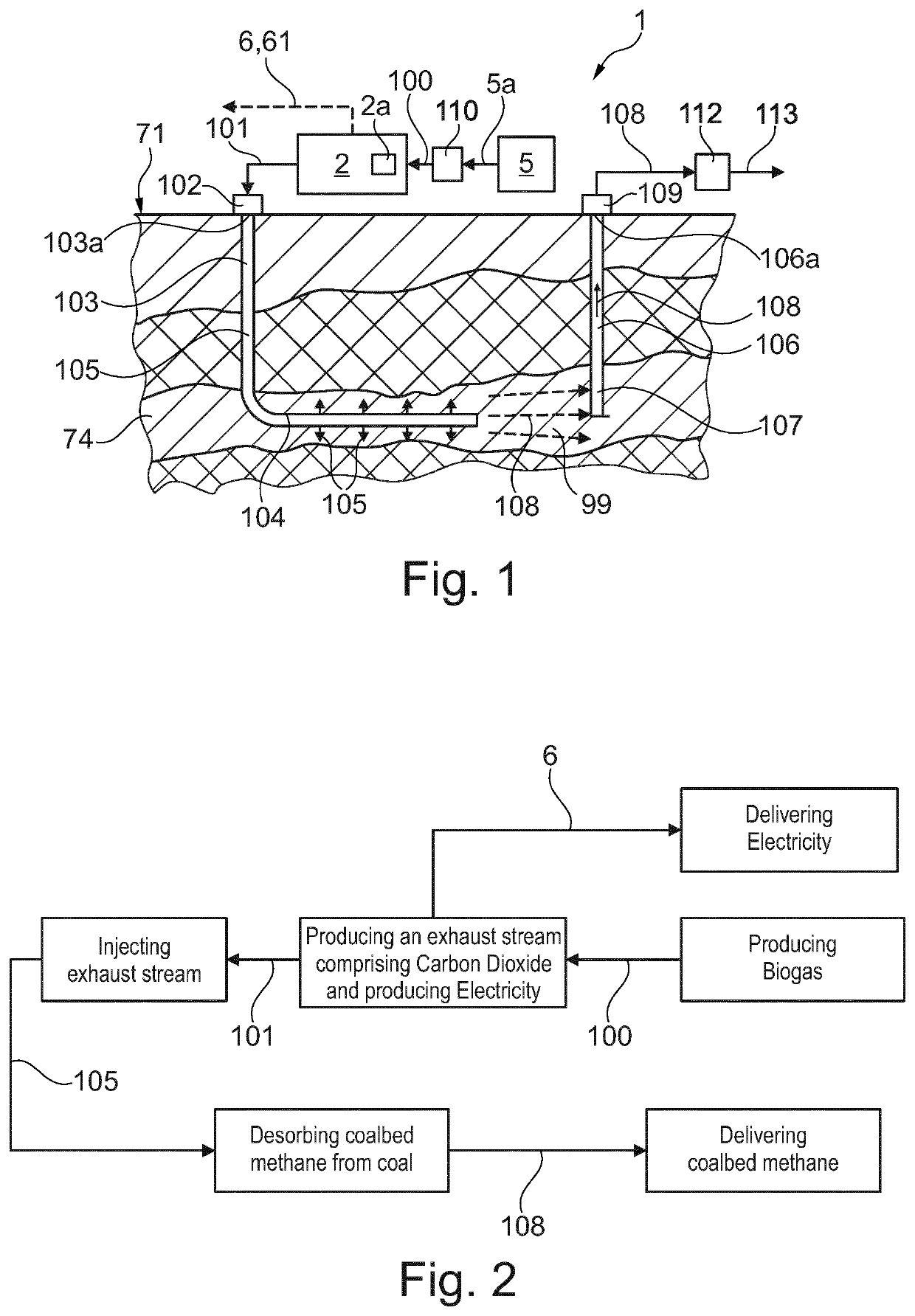
[0063]FIG. 1 shows a system 1 and method for removing CO2 and for producing coal bed methane (CBM). The system 1 comprises an SOFC system 2 comprising a solid oxide fuel cell 2a. Exemplary embodiments of suitable SOFC systems 2 are disclosed in FIGS. 8 and 9 in detail. A biogas reactor 5 produces a biogas 5a from for example biological waste, plant biomass collected from the earth's surface or phytoplankton biomass collected from the ocean. The biogas 5a is preferably purified in a pre-treatment unit 110 and leaves the pre-treatment unit as a gaseous hydrocarbon feed 100. The gaseous hydrocarbon feed 100 is fed to the anode side of the solid oxide fuel cell 2a. The gaseous hydrocarbon feed 100 is at least partially oxidized in the solid oxide fuel cell 2a, and leaves the solid oxide fuel cell 2a as an anode exhaust stream 101, the solid oxide fuel cell 2a thereby producing electricity 6, 61. The anode exhaust stream 101 serves as an injection gas 105 which through a wellhead 102 and...

second embodiment

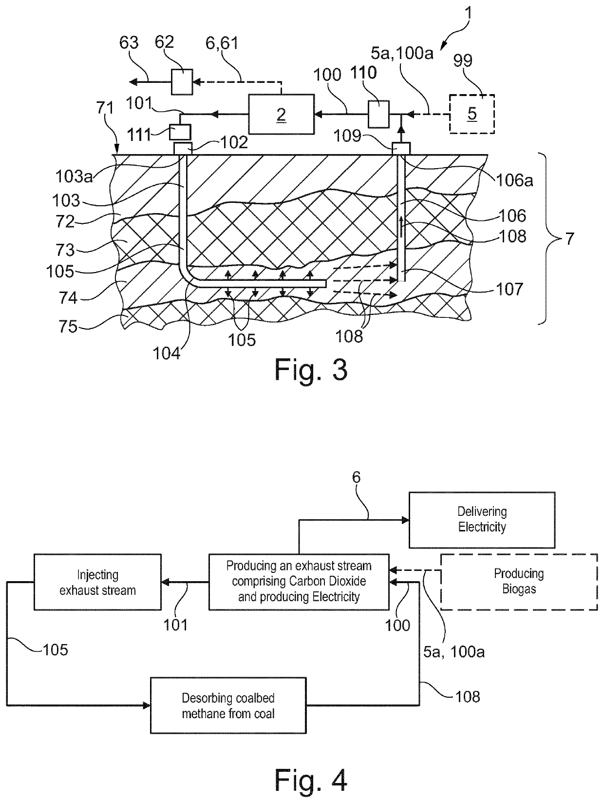
[0070]FIG. 3 shows a system 1 and method for removing CO2 and for producing CBM. In contrast to the embodiment disclosed in FIG. 1, in the system and method disclosed in FIG. 3, at least part of the production gas 108 is fed back to the SOFC system 2 and used as the gaseous hydrocarbon feed 100, which is fed to the solid oxide fuel cell 2a. The production gas 108 may directly be fed to the solid oxide fuel cell 2a. In an advantageous embodiment the production gas 108 is purified in a pre-treatment unit 110 before feeding the pretreated production gas 108 as the gaseous hydrocarbon feed 100 into the anode side of the solid oxide fuel cell 2a. The solid oxide fuel cell 2a thereby producing electricity 6 and the anode exhaust stream 101. A compressor 111 may be used to compress the anode exhaust stream 101 before feeding it into the first well head 102. The method for feeding the anode exhaust stream 101 into the first well head 102 and for collecting the production gas 108 at the seco...


PUM

PropertyMeasurementUnit
GWPaaaaaaaaaa
electrical energyaaaaaaaaaa
adsorptionaaaaaaaaaa

Abstract

The method and system for removing CO2 from the atmosphere or the ocean having the steps of, feeding a solid oxide fuel cell (SOFC) system with a gaseous hydrocarbon feed, converting the gaseous hydrocarbon feed in the SOFC system into an anode exhaust stream having carbon dioxide CO2, the SOFC system thereby producing electricity; injecting the anode exhaust stream as an injection gas into an underground coal bed; in the underground coal bed the injection gas causing coal bed methane (CBM) to desorb from the coal and CO2 to adsorb onto the coal; extracting the coal bed methane (CBM) from the underground coal bed; and discharging a production gas having the coal bed methane (CBM) from the underground coal bed.

Description

FIELD OF THE INVENTION[0001]The field of invention relates to a method and a system for removing carbon dioxide from the atmosphere or the ocean.BACKGROUND OF THE INVENTION[0002]Global warming, triggered by a substantial increase in anthropogenic CO2 and other greenhouse gas emissions into the atmosphere, represents one of the most pressing existential threats to civilization and to life on earth. Humanity must therefore urgently redirect its efforts and resources to reducing CO2 emission and to removing excess anthropogenic CO2 that has already been released into the atmosphere.Technical Problem to be Solved[0003]The objective of the present invention is an improved method and system for removing carbon dioxide CO2 from the atmosphere or the ocean. A further objective of the present invention is to provide an energy-efficient method and system that allows removing high amounts of CO2 from the atmosphere or the ocean. A further objective of the present invention relates to a method ...

Claims


Application Information

Patent Timeline
Patent Type & Authority Applications(United States)
IPC IPC(8): B01D53/32C25B5/00C25B1/50B01D53/04E21B41/00
CPCB01D53/326C25B5/00C25B1/50B01D2258/05E21B41/0064B01D2257/504B01D2258/0208B01D53/0446H01M8/04089H01M8/04201H01M8/0618H01M8/0668H01M8/2425H01M2008/1293E21B41/0057E21B43/164B01D53/04B01D2253/102Y02C20/20Y02P90/70Y02P70/50
Inventor ITANI, RACHADKOCH, TOBIASRAVAGNI, ALBERTOBUCHELI, OLIVIER
Owner EZ ENERGIES GMBH
Why Eureka
Try Eureka