Electricity-steam two-purpose high-temperature deoiling device

A high-temperature degreasing and dual-purpose technology, applied in liquid separation, chemical instruments and methods, liquid separation auxiliary equipment, etc., can solve the problems of inability to achieve the best state of oil-water separation, real-time monitoring of degreasing tank temperature, and poor control. To achieve the effect of diversification of heating methods, saving time of sewage discharge and fast heating speed

Inactive Publication Date: 2017-03-29
JIANGSU SULI MACHINERY SHARES CO LTD
View PDF0 Cites 0 Cited by
  • Summary
  • Abstract
  • Description
  • Claims
  • Application Information

AI Technical Summary

Problems solved by technology

[0002] Automobile coating pretreatment is an important process line, and degreasing is the primary key process. In order to obtain good coating quality and meet the requirements of coating corrosion resistance and appearance decoration, it is necessary to separate oil and water from the degreasing liquid. The oil device is widely used due to its low investment, simple structure and easy operation, but there are the following disadvantages when using the traditional high-temperature oil removal device: generally, steam heating tubes are used for heating, the heating speed is relatively slow, and the heating method is single. Once damaged, the work needs to be stopped; at the same time, it is impossible to monitor the temperature in the degreasing tank in real time, and the oil-water separation cannot reach the best state; in addition, due to the existence of multiple cavities in the process of removing sludge, each cavity needs to be drained separately , the sewage discharge is more troublesome, the sewage discharge takes a long time, and the liquid in the degreasing tank is easy to be discharged together with the sludge during the sewage discharge, which is not easy to control and cannot meet the use requirements of the enterprise

Method used


Image

  • Electricity-steam two-purpose high-temperature deoiling device
  • Electricity-steam two-purpose high-temperature deoiling device

Examples


Embodiment Construction

[0009] The specific content of the present invention will be described in detail below in conjunction with the accompanying drawings and specific embodiments.

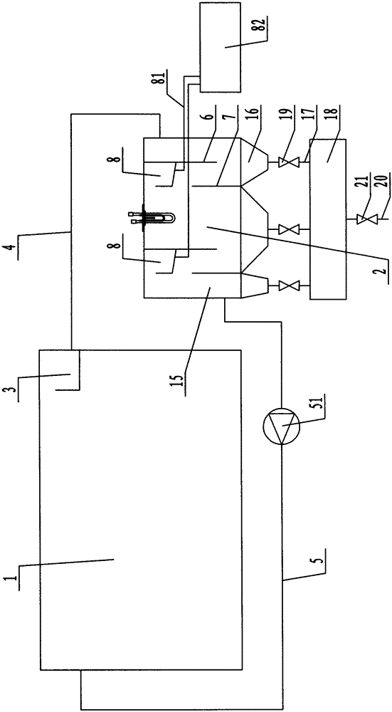
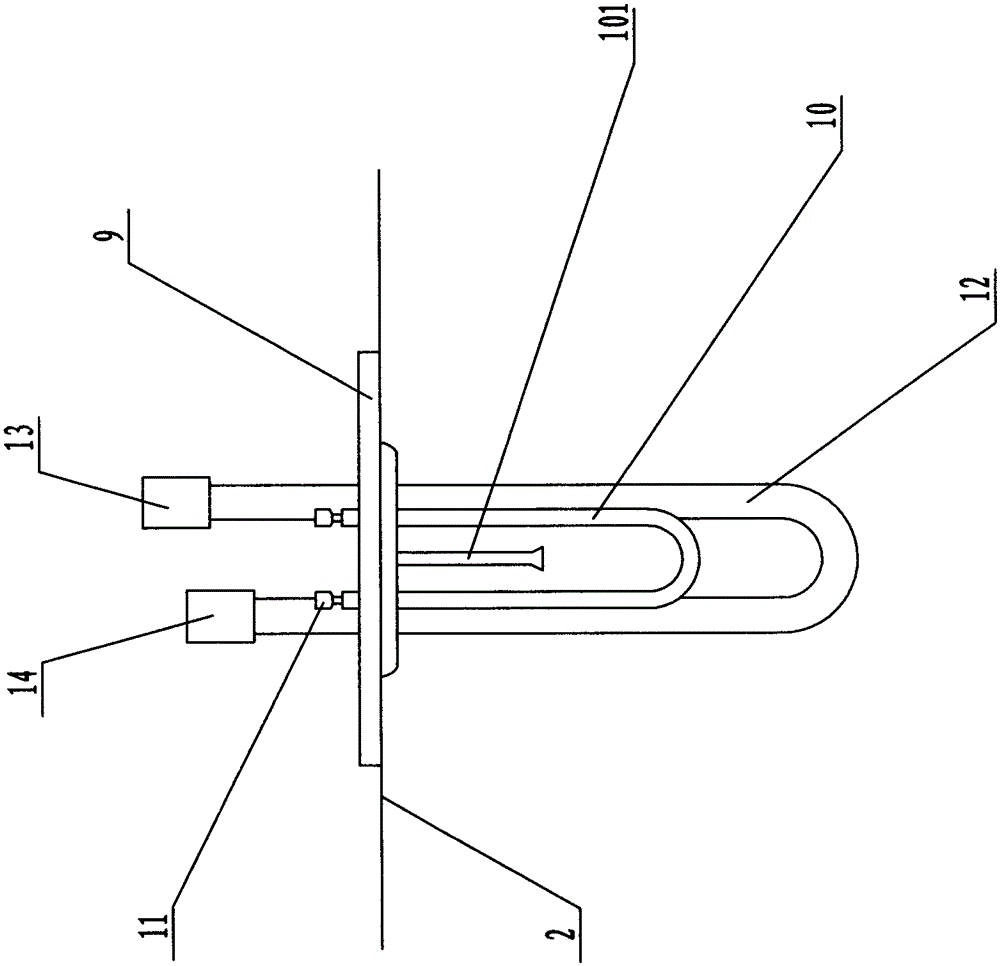
[0010] Such as figure 1 , figure 2 As shown, the electric dual-purpose high-temperature degreasing device includes: a degreasing main tank 1 and a degreasing auxiliary tank 2, and a first overflow tank 3 is arranged at the upper end of one side of the degreasing main tank 1, and the first overflow tank 3 communicate with the upper end of one side of the degreasing auxiliary tank 2 through the first pipeline 4, and the other lower end of the degreasing auxiliary tank 2 communicates with the other upper end of the degreasing main tank 1 through the second pipeline 5. The second pipeline 5 is provided with a water pump 51. In the degreasing auxiliary tank 2, two upper partitions 6 and two lower partitions 7 are arranged. The upper ends of the two upper partitions 6 and the lower ends of the two lower partitions 7 are co...


PUM


Abstract

The invention discloses an electricity-steam two-purpose high-temperature deoiling device. The electricity-steam two-purpose high-temperature deoiling device comprises a main degreasing tank and an auxiliary degreasing tank, a first overflow tank is arranged at the upper end of one side of the main degreasing tank and communicates with the upper end of one side of the auxiliary degreasing tank through a first pipeline, the lower end of the other side of the auxiliary degreasing tank communicates with the upper end of the other side of the main degreasing tank through a second pipeline, and a water pump is arranged on the second pipeline; two upper partition plates and two lower partition plates are arranged in the auxiliary degreasing tank, the upper ends of the upper partition plates and the lower ends of the lower partition plates are connected with the auxiliary degreasing tank, the lower ends of the upper partition plates and the upper ends of the lower partition plates are separated from the auxiliary degreasing tank, the upper partition plates and the lower partition plates are arranged in a staggered mode, the upper ends of the upper partition plates are each provided with a second overflow tank, and the portion, between the upper partition plates, of the auxiliary degreasing tank is provided with a heating device.

Description

technical field [0001] The invention relates to a coating degreasing device, in particular to an electrical dual-purpose high-temperature degreasing device. Background technique [0002] Automobile coating pretreatment is an important process line, and degreasing is the primary key process. In order to obtain good coating quality and meet the requirements of coating corrosion resistance and appearance decoration, it is necessary to separate oil and water from the degreasing liquid. The oil device is widely used due to its low investment, simple structure and easy operation, but there are the following disadvantages when using the traditional high-temperature oil removal device: generally, steam heating tubes are used for heating, the heating speed is relatively slow, and the heating method is single. Once damaged, the work needs to be stopped; at the same time, it is impossible to monitor the temperature in the degreasing tank in real time, and the oil-water separation canno...

Claims


Application Information

Patent Timeline
Patent Type & Authority Applications(China)
IPC IPC(8): B01D17/032B01D17/12
Inventor 张晓同郭友春郭伟颜中玉陈燕
Owner JIANGSU SULI MACHINERY SHARES CO LTD
Why Eureka
Try Eureka