A steam turbine blade forming device

A technology for steam turbine blades and forming devices, which is applied to operating devices, hammer driving devices, forging/pressing/hammer devices, etc., can solve the problems of high energy consumption and low processing efficiency, and achieve the effect of improving work efficiency and reducing labor.

Active Publication Date: 2019-02-12
德阳瑞能电力科技有限公司
View PDF7 Cites 0 Cited by
  • Summary
  • Abstract
  • Description
  • Claims
  • Application Information

AI Technical Summary

Problems solved by technology

[0004] In order to overcome the defects of low processing efficiency and high energy consumption of existing steam turbine blades, the invention provides a steam turbine blade forming device, which can realize continuous forming of steam turbine blades and improve the forming efficiency

Method used


Image

  • A steam turbine blade forming device
  • A steam turbine blade forming device
  • A steam turbine blade forming device

Examples


Embodiment 1

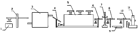
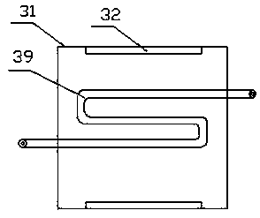
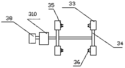
[0045] This embodiment includes a blank warehouse 1, a conveyor, a heating furnace 3, a blank forging machine 5, a blade forming machine 7, a demoulding machine 9 and an edge trimming machine 11; there are four conveyors, which are respectively the first conveyor 2 , the second conveyor 6, the third conveyor 8 and the fourth conveyor 10, the first conveyor 2 is installed between the blank warehouse 1 and the heating furnace 3, the second conveyor 6 is installed between the blank forging machine 5 and the blade forming Between the machine 7, the third conveyor 8 is installed between the blade forming machine 7 and the demoulding machine 9, and the fourth conveyor 10 is installed between the demoulding machine and the 9 edge trimmer 11; the heating furnace 3 and the blank A conveyor ramp 4 is installed between the forging machines 5. The first conveyor 2 transports the blanks in the blank storehouse 1 to the feed port of the heating furnace 3. After being heated, it is sent out f...

Embodiment 2

[0047] This embodiment includes a blank warehouse 1, a conveyor, a heating furnace 3, a blank forging machine 5, a blade forming machine 7, a demoulding machine 9 and an edge trimming machine 11; there are four conveyors, which are respectively the first conveyor 2 , the second conveyor 6, the third conveyor 8 and the fourth conveyor 10, the first conveyor 2 is installed between the blank warehouse 1 and the heating furnace 3, the second conveyor 6 is installed between the blank forging machine 5 and the blade forming Between the machine 7, the third conveyor 8 is installed between the blade forming machine 7 and the demoulding machine 9, and the fourth conveyor 10 is installed between the demoulding machine and the 9 edge trimmer 11; the heating furnace 3 and the blank A conveyor ramp 4 is installed between the forging machines 5. The first conveyor 2 transports the blanks in the blank storehouse 1 to the feed port of the heating furnace 3. After being heated, it is sent out f...

Embodiment 3

[0052] This embodiment includes a blank warehouse 1, a conveyor, a heating furnace 3, a blank forging machine 5, a blade forming machine 7, a demoulding machine 9 and an edge trimming machine 11; there are four conveyors, which are respectively the first conveyor 2 , the second conveyor 6, the third conveyor 8 and the fourth conveyor 10, the first conveyor 2 is installed between the blank warehouse 1 and the heating furnace 3, the second conveyor 6 is installed between the blank forging machine 5 and the blade forming Between the machine 7, the third conveyor 8 is installed between the blade forming machine 7 and the demoulding machine 9, and the fourth conveyor 10 is installed between the demoulding machine and the 9 edge trimmer 11; the heating furnace 3 and the blank A conveyor ramp 4 is installed between the forging machines 5. The first conveyor 2 transports the blanks in the blank storehouse 1 to the feed port of the heating furnace 3. After being heated, it is sent out f...


PUM


Abstract

The invention discloses a steam turbine vane molding device. The steam turbine vane molding device comprises a workblank bank, conveyors, a heating furnace, a workblank forging machine, a vane molding machine, a demolding machine and an edge trimming machine. Each conveyor comprises a vertical rod, a transverse rod and an electromagnet device. Each transverse rod is fixed to the corresponding vertical rod and provided with a transverse slide rail. An inclined conveying plate is mounted between the heating furnace and the workblank forging machine. Workblank materials in the workblank bank are conveyed to a feeding opening of the heating furnace, heated and then sent out of a discharging opening of the heating furnace; the workblank materials fall onto the inclined conveying plate and then slide down onto the workblank forging machine for workblank forging; and the workblank materials are conveyed onto the vane molding machine for vane forging molding, the demolding machine conducts demolding, and then edge trimming is conducted. By means of the steam turbine vane molding device, continuous molding of steam turbine vanes can be achieved, and molding efficiency is improved.

Description

technical field [0001] The invention relates to a manufacturing equipment of a steam turbine blade, in particular to a steam turbine blade forming device. Background technique [0002] The blade of the steam turbine is an indispensable part of the steam turbine, the blade of the steam turbine. Commonly used materials for steam turbine blades are: (1): Chromium stainless steel 1Cr13 and 2Cr13 are martensitic heat-resistant steels, which not only have sufficient strength at room temperature and working temperature, but also have high corrosion resistance and vibration reduction. It is the most widely used steam turbine material in the world. (2): Strengthened chromium stainless steel makes up for the shortcomings of 1Cr13 chromium stainless steel with low thermal strength, and adds molybdenum, tungsten, vanadium, niobium, boron, etc. to it. (3): Low-alloy pearlitic heat-resistant steel is used to manufacture moving blades and stationary blades at all levels of medium-pressur...

Claims


Application Information

Patent Timeline
Patent Type & Authority Patents(China)
IPC IPC(8): B21K3/04B21K27/00B21K29/00B21J7/04B21J7/46B21J13/10B21J17/00B21J13/00B21J13/14
CPCB21J7/04B21J7/46B21J13/00B21J13/10B21J13/14B21J17/00B21K3/04B21K27/00B21K29/00
Inventor 李杰陆晓阳
Owner 德阳瑞能电力科技有限公司
Why Eureka
Try Eureka