
Engraving precision improvement device and axis and table adjustment device for stereo engraving machine

A three-dimensional engraving machine and shaft center technology, applied in the field of engraving machines, can solve problems such as insufficient engraving accuracy, and achieve the effect of improving engraving accuracy and facilitating loading and unloading

Inactive Publication Date: 2017-03-29
蒙建宇
View PDF7 Cites 4 Cited by
  • Summary
  • Abstract
  • Description
  • Claims
  • Application Information

AI Technical Summary

Problems solved by technology

[0004] In order to achieve the above purpose, the technical solution adopted by the present invention is divided into two themes. The technical problem to be solved by the first theme solution is: the reducer has a certain backlash due to reasons such as structure and processing technology, resulting in insufficient engraving accuracy.

Method used


Image

  • Engraving precision improvement device and axis and table adjustment device for stereo engraving machine
  • Engraving precision improvement device and axis and table adjustment device for stereo engraving machine
  • Engraving precision improvement device and axis and table adjustment device for stereo engraving machine

Examples


Embodiment 1

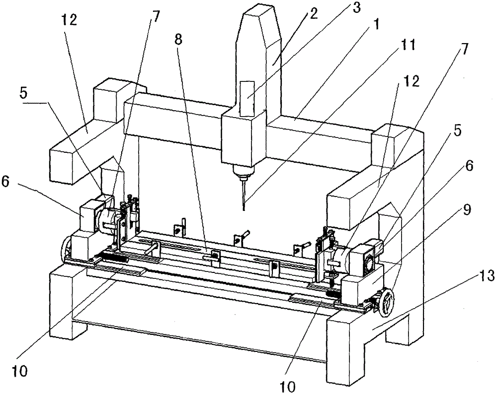
[0016] Embodiment 1 An embodiment of improving engraving precision. See Picture 1-1 , the output shaft of the servo motor is connected with the reducer, the reducer is installed on the support, and the support is located on the dovetail lower frame, and the present embodiment links to each other with two sets of servo motors and the precision reducer. After the power is turned on, the two sets of servo motors start at the same time, which can reduce the backlash of the reducer and improve the engraving accuracy of the three-dimensional engraving machine.

Embodiment 2

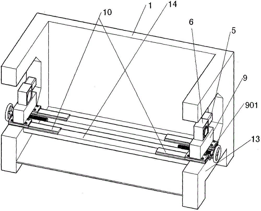
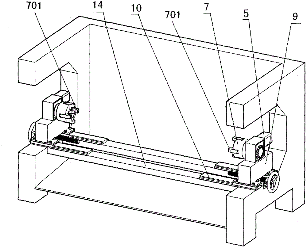
[0017] Embodiment two, three-dimensional engraving. Install the centering chuck on the output shaft of the reducer, set the trapezoidal clip on the centering chuck, install the reducer on the machine base, the machine base is located under the dovetail upper frame, and set the bottom plate under the machine base, the bottom plate and the guide rail It fits and can slide left and right along the guide rail. The bottom plate and guide rail are located on the upper part of the dovetail lower frame, and the two centering chucks can be moved to a position suitable for clamping the object to be carved. See figure 2 , Figure 2-1 . Place the object to be engraved on the trapezoidal clips of the two centering chucks, and when working, the motor drives the reducer, and the reducer drives the chuck to rotate, so the object to be engraved cooperates with the engraving on the Z-axis slide table according to the signal of the computer The knife rotates and rotates or turns to achieve t...

Embodiment 3

[0018] Embodiment 3, in practice, in many occasions, only semi-stereo arc carvings such as Roman columns, marble door frames, etc., so the inventor invented the axis-adjusting table top device of this embodiment according to the needs of different customers, which is in the embodiment On the basis of the second, additional components such as eccentric plate surface, clamping plate, positioning plate, positioning screw, screw, insert, plate groove, clamping block, fixed plate, and combined screw are added. See image 3 , Figure 4 . Use the height adjusting screw and positioning screw to adjust the rotation axis of the engraved object from the Z axis and the Y axis to align with the center of rotation, that is, the center of the centering chuck.


PUM


Abstract

The invention discloses an engraving precision improvement device and an axis and table adjustment device for a stereo engraving machine and belongs to the technical field of engraving machines. The invention has two topics, wherein the first is the engraving precision improvement device which is characterized in that two sets of independent stepping or servo motors are utilized to drive precision reducers, so that the purposes of reducing and canceling back clearances which exist due to structures of the reducers and improving the engraving precision are achieved; and the second is the axis and table adjustment device which comprises centering chucks, trapezoidal clamping pieces, engine bases, guide rails, an eccentric board and clamping plates. The engraving precision improvement device and the axis and table adjustment device for the stereo engraving machine have the following beneficial effects: by adoption of the engraving machine, engraved objects rotate and revolve accurately, so that the engraving precision is improved; and the axis and table adjustment device can adjust the axis, the height and the length according to object sizes, so that the engraved objects can be conveniently loaded and unloaded.

Description

technical field [0001] The invention relates to an engraving precision device and an axis-adjusting table top device of a three-dimensional engraving machine, belonging to the technical field of engraving machines. Background technique [0002] The three-dimensional engraving machines currently on the market have poor engraving accuracy; the clamping is not tight and too laborious, especially when clamping heavy workpieces such as stone and wood processing, it is more time-consuming and laborious. Contents of the invention [0003] The purpose of the present invention is to improve the engraving precision of the three-dimensional engraving machine, and provide an adjustable axis table top device that can control the rotation speed. The purpose of engraving precision. [0004] In order to achieve the above purpose, the technical solution adopted by the present invention is divided into two themes. The technical problem to be solved by the first theme solution is: the reduc...

Claims


Application Information

Patent Timeline
Patent Type & Authority Applications(China)
IPC IPC(8): B44B1/00B44B1/06
CPCB44B1/006B44B1/06B44B2700/12
Inventor 蒙建宇
Owner 蒙建宇
Learn More