Surrounding rock stress measurement system

A measurement system and technology of surrounding rock stress, applied in the direction of hydraulic/pneumatic measurement, etc., can solve the problems of judgment error, stress data acquisition error, deviation of the force measurement direction of surrounding rock stress meter from the preset direction, etc. Small measurement error, guaranteed accuracy, and the effect of accurate measurement of surrounding rock stress

Active Publication Date: 2017-03-29
CHINA UNIV OF MINING & TECH
View PDF8 Cites 3 Cited by
  • Summary
  • Abstract
  • Description
  • Claims
  • Application Information

AI Technical Summary

Problems solved by technology

[0004] In the prior art, the mining stress is usually collected by drilling surrounding rock stress gauges, that is, after drilling a hole in the coal or rock mass where the stress is to be measured, the stress value is collected by installing a guide rod into the stress gauge. Due to uneven drilling plane or uneven force during drilling, the drilling deviates from the predetermined direction. The deeper the drilling depth, the more obvious the deviation is, especially the inclined drilling with a certain angle with the horizontal plane is more difficult to ensure the drilling direction, which is extremely difficult. It is easy to cause the stress measured by the surrounding rock stress gauge to be not the stress in the required direction. The more the drilling direction deviates and the deeper the drilling depth is, the greater the error of the measured stress is, which easily leads to misjudgment due to numerical deviation; in addition, the traditional It is difficult to accurately ensure th

Method used


Image

  • Surrounding rock stress measurement system
  • Surrounding rock stress measurement system
  • Surrounding rock stress measurement system

Examples


Embodiment Construction

[0025] The present invention will be further described below in conjunction with the accompanying drawings (hereinafter, the direction in which the stress gauge body 1 is placed in the borehole is used as the front description).

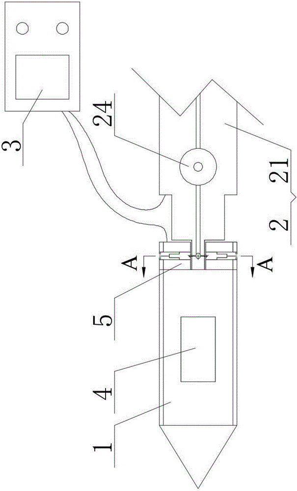
[0026] Such as figure 1 As shown, the surrounding rock stress measurement system includes a stress gauge body 1 , an installation guide rod 2 and a display instrument box 3 .

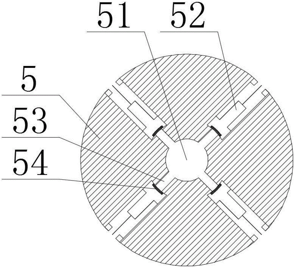
[0027] The stress gauge body 1 has a cylindrical shape as a whole, and its front end is set in a conical structure, which is convenient for advancing into the borehole. The stress gauge body 1 is provided with a pressure chamber inside, and the stress gauge body 1 is also provided with a pressure block 4 and the stress gauge fixing device 5; the pressure bearing block 4 is sealed and embedded in the stress gauge body 1 through the guide structure arranged in the radial direction on the stress gauge body 1, and the embedded end of the pressure bearing block 4 is connected to th...


PUM


Abstract

The present invention discloses a surrounding rock stress measurement system. The surrounding rock stress measurement system includes a stress gauge body, a mounting guide rod and a display instrument box; the stress gauge body is provided with a pressure bearing block and a stress gauge fixing device; the stress gauge fixing device comprises a guide rod mounting hole, a positioning cylinder and a guide channel; the mounting guide rod comprises a guide rod and a connecting guide rod; the front end of the guide rod is provided with a positioning shaft end; and the positioning shaft end is provided with a positioning pin which is telescopically controlled by a telescopic control mechanism, wherein the positioning pin is corresponding to the guide channel; and the display instrument box comprises a controller, a display screen, a hydraulic pump station, a hydraulic control valve group, a pressure bearing block control loop, a positioning cylinder control loop and a stress numerical value acquisition calculation loop. With the surrounding rock stress measurement system adopted, the pose of the stress gauge body in a borehole can be accurately determined, and the stress gauge body can be positioned in the borehole, and therefore, measurement errors caused by the deviation of the borehole and axial deflection in the embedding process of a surrounding rock stress gauge can be decreased to the greatest extent, and surrounding rock stress can be accurately measured. The surrounding rock stress measurement system of the invention is especially for coal mining stress deep hole data acquisition and monitoring.

Description

technical field [0001] The invention relates to a stress measurement system, in particular to a surrounding rock stress measurement system suitable for underground coal mines, and belongs to the technical field of coal mine rock mass stress measurement. Background technique [0002] The measurement and application of in-situ stress has played an increasingly important role not only in structural geology, earthquake prediction and geodynamics research, but also in production practices such as mining, underground engineering and energy development. and engineering attention. [0003] For mining, excavating roadways and carrying out mining work is called mining of coal or surrounding rock. After mining, the stress balance state of the original rock mass is destroyed, causing the stress redistribution inside the rock mass, and the redistributed stress When the ultimate strength of coal and rock is exceeded, the coal and rock around the roadway or coal mining face will be damage...

Claims


Application Information

Patent Timeline
IPC IPC(8): G01L1/02
CPCG01L1/02
Inventor 王旭锋张东升王文强曹文豪秦冬冬李鹏
Owner CHINA UNIV OF MINING & TECH
Why Eureka
Try Eureka