Optical image capturing system
一种光学成像系统、成像面的技术,应用在光学、光学元件、仪器等方向,能够解决无法满足摄影要求等问题,达到佳光路调节能力、提升成像质量的效果
- Summary
- Abstract
- Description
- Claims
- Application Information
AI Technical Summary
Problems solved by technology
Method used
Image


Examples
no. 1 example
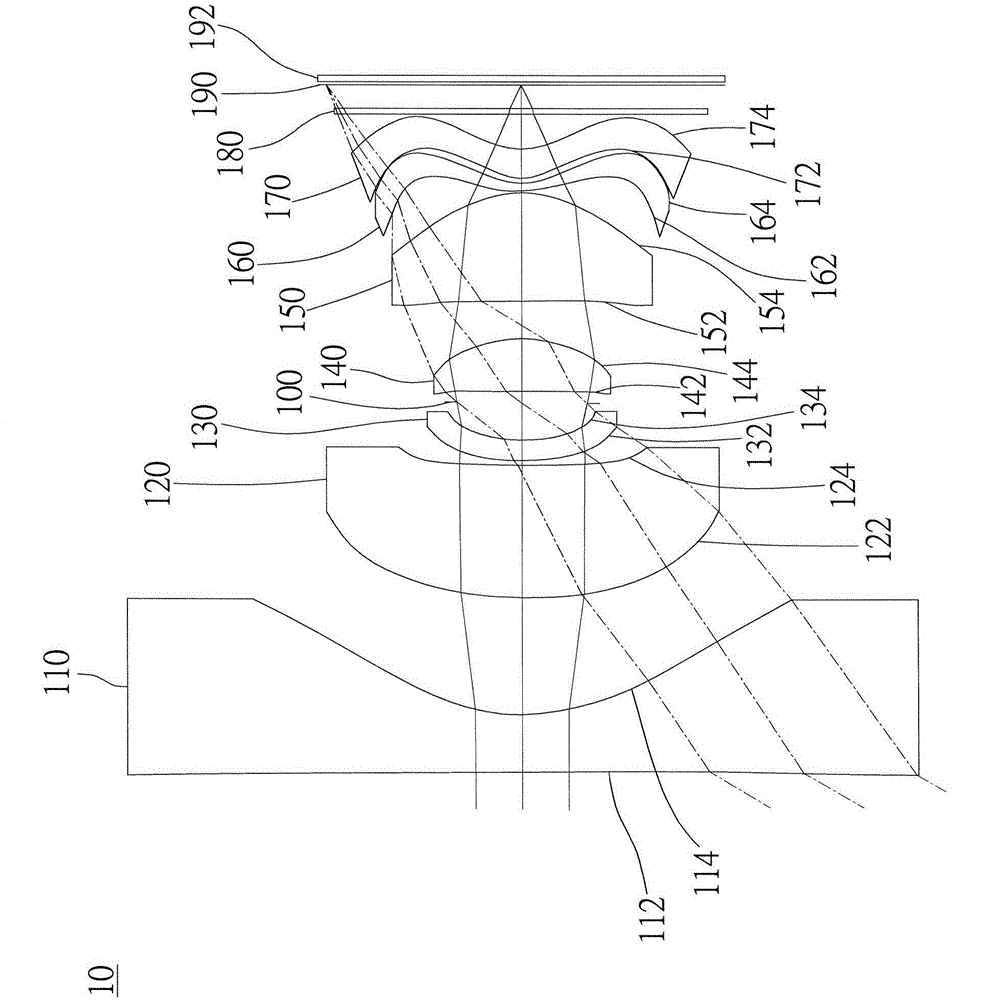
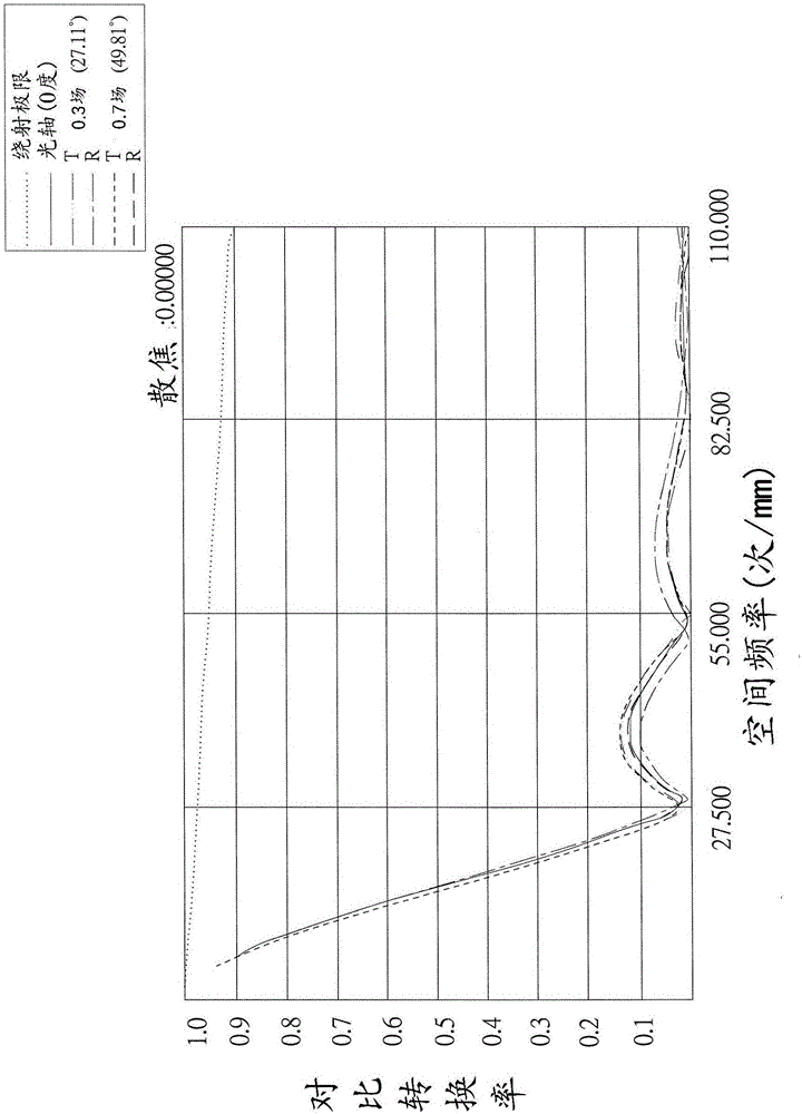
[0171] like Figure 1A and Figure 1B shown, where Figure 1A is a schematic diagram of an optical imaging system according to the first embodiment of the present invention, Figure 1B From left to right are the spherical aberration, astigmatism and optical distortion curves of the optical imaging system of the first embodiment. Figure 1C is the visible light spectrum modulation conversion characteristic diagram of this embodiment; Figure 1D It is the infrared spectrum modulation conversion characteristic diagram of this embodiment. Depend on Figure 1A It can be seen that the optical imaging system includes the first lens 110, the aperture 100, the second lens 120, the third lens 130, the fourth lens 140, the fifth lens 150, the sixth lens 160 and the seventh lens in order from the object side to the image side. 170 , an infrared filter 180 , an imaging surface 190 and an image sensing element 192 .
[0172] The first lens 110 has negative refractive power and is made of...
no. 2 example
[0241] like Figure 2A and Figure 2B shown, where Figure 2A It is a schematic diagram of an optical imaging system according to the second embodiment of the present invention, Figure 2B From left to right are the spherical aberration, astigmatism and optical distortion curves of the optical imaging system of the second embodiment. Figure 2C It is a lateral aberration diagram of the optical imaging system of the second embodiment at a field of view of 0.7. Depend on Figure 2A It can be seen that the optical imaging system includes the first lens 210, the aperture 200, the second lens 220, the third lens 230, the fourth lens 240, the fifth lens 250, the sixth lens 260 and the seventh lens in order from the object side to the image side. 270 , an infrared filter 280 , an imaging surface 290 and an image sensing element 292 .
[0242] The first lens 210 has positive refractive power and is made of plastic material. The object side 212 is convex, and the image side 214 is...
no. 3 example
[0266] like Figure 3A and Figure 3B shown, where Figure 3A It is a schematic diagram of an optical imaging system according to the third embodiment of the present invention, Figure 3B From left to right are the spherical aberration, astigmatism and optical distortion curves of the optical imaging system of the third embodiment. Figure 3C It is a lateral aberration diagram of the optical imaging system of the third embodiment at a field of view of 0.7. Depend on Figure 3A It can be seen that the optical imaging system includes the first lens 310, the aperture 300, the second lens 320, the third lens 330, the fourth lens 340, the fifth lens 350, the sixth lens 360 and the seventh lens in order from the object side to the image side 370 , an infrared filter 380 , an imaging surface 390 and an image sensor 392 .
[0267] The first lens 310 has a positive refractive power and is made of plastic. The object side 312 is convex, and the image side 314 is concave, both of wh...
PUM
 Abstract
Description
Claims
Application Information
 - R&D
- Intellectual Property
- Life Sciences
- Materials
- Tech Scout
- Unparalleled Data Quality
- Higher Quality Content
- 60% Fewer Hallucinations
Browse by: Latest US Patents, China's latest patents, Technical Efficacy Thesaurus, Application Domain, Technology Topic, Popular Technical Reports.
© 2025 PatSnap. All rights reserved.Legal|Privacy policy|Modern Slavery Act Transparency Statement|Sitemap|About US| Contact US: help@patsnap.com