
Real-time three-dimensional laser fluorescence microscopic imaging device

A microscopic imaging, real-time three-dimensional technology, applied in microscopes, optics, optical components, etc., can solve the problem of low overall energy efficiency

Active Publication Date: 2017-03-29
SHANGHAI INST OF OPTICS & FINE MECHANICS CHINESE ACAD OF SCI
View PDF12 Cites 26 Cited by
  • Summary
  • Abstract
  • Description
  • Claims
  • Application Information

AI Technical Summary

Problems solved by technology

However, the twisted grating proposed by Blanchard et al. was originally designed based on the amplitude type grating, therefore, its main diffraction energy is concentrated in the zero order, and the overall energy efficiency is very low

Method used


Image

  • Real-time three-dimensional laser fluorescence microscopic imaging device
  • Real-time three-dimensional laser fluorescence microscopic imaging device
  • Real-time three-dimensional laser fluorescence microscopic imaging device

Examples


Embodiment

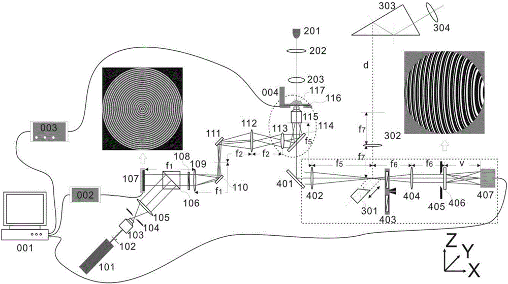
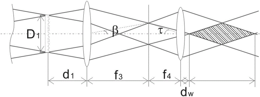
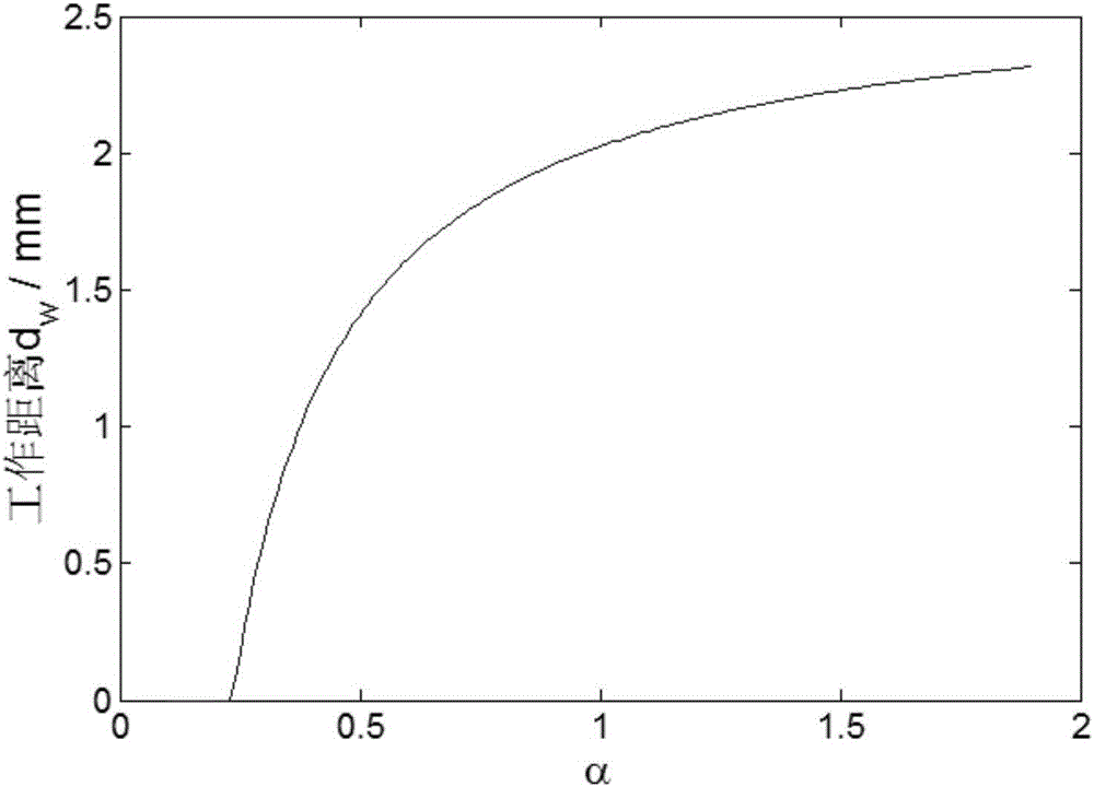
[0045] Taking the focusing lens with NA=0.85 as an example, a specific implementation scheme of a real-time three-dimensional laser fluorescence imaging device is proposed below.

[0046] The laser used is a tunable femtosecond laser with a wavelength in the range of 690 to 1020 nanometers (including a parametric oscillator for wavelength tuning). The laser is a fundamental mode horizontally polarized output, and its beam waist radius is 1.5mm. The spatial light modulator used is HoloEye, Plute VIS, the working wavelength is 400-1100 nanometers, the number of pixels is 1920×1080, and the single pixel size is 8 microns. For the sake of brevity, we only consider that the fluorescence wavelength center is 480 nm, the spectral width is set to ±30 nm, and the corresponding excitation light center wavelength is 960 nm. In fact, due to its tunable excitation wavelength, the device can achieve common fluorescence wavelength bands such as central wavelengths of 450 nanometers, 480 nanomet...


PUM


Abstract

The invention relates to a real-time three-dimensional laser fluorescence microscopic imaging device. The real-time three-dimensional laser fluorescence microscopic imaging device is compatible with a traditional bright field illumination microscopic imaging working mode. The real-time three-dimensional laser fluorescence microscopic imaging device is divided into a laser excitation module, a bright field imaging illumination module, a digital detection module, an eyepiece observation module and a control module according to functions. A spatial light modulator is adopted to load a pyramid phase, so that a Gaussian-Bessel illumination light field can be generated at the backfield of a focusing objective lens. In a detection optical path, a twisted Dammann grating is additionally adopted so as to realize simultaneous imaging of a multi-surface object, fluorescence collected from the objective lens simultaneously images a plurality of axial planes to an electron-enhanced CCD detection surface through a multi-surface imaging technology, and therefore, real-time three-dimensional fluorescence imaging can be realized. The real-time three-dimensional fluorescence imaging technique has an important practical value in biological living tissue and living cell microscopic imaging.

Description

Technical field [0001] The invention relates to a novel three-dimensional microscopic imaging technology, in particular to a real-time three-dimensional fluorescence microscopic imaging device. Background technique [0002] Optical imaging technology is a non-contact, non-destructive imaging technology, so it has important applications in imaging of living organisms or living cells. In addition to non-contact and non-destructive detection, in vivo biological imaging also requires real-time dynamic three-dimensional imaging information. At present, this kind of real-time 3D imaging technology is generally based on spatial scanning of galvanometers or piezoelectric ceramics or frequency domain scanning of broadband light sources. These dynamic 3D imaging technologies are dynamic imaging based on scanning technology, not real-time dynamic imaging in the true sense. In 1999, the British scientist Blanchard et al. [Appl. Opt. 38, 6692 (1999)] proposed a 4D imaging technology that si...

Claims


Application Information

Patent Timeline
Patent Type & Authority Applications(China)
IPC IPC(8): G02B21/00G02B21/24
CPCG02B21/0076G02B21/242
Inventor 余俊杰周常河项长铖吴俊
Owner SHANGHAI INST OF OPTICS & FINE MECHANICS CHINESE ACAD OF SCI
Learn More