A low-delay method and device in wireless communication
A wireless communication, low-latency technology, applied in the field of low-latency transmission based on long-term evolution, can solve problems such as LTE long-air interface delay, and achieve the effect of improving transmission efficiency
- Summary
- Abstract
- Description
- Claims
- Application Information
AI Technical Summary
Problems solved by technology
Method used
Image
Examples
Embodiment 1
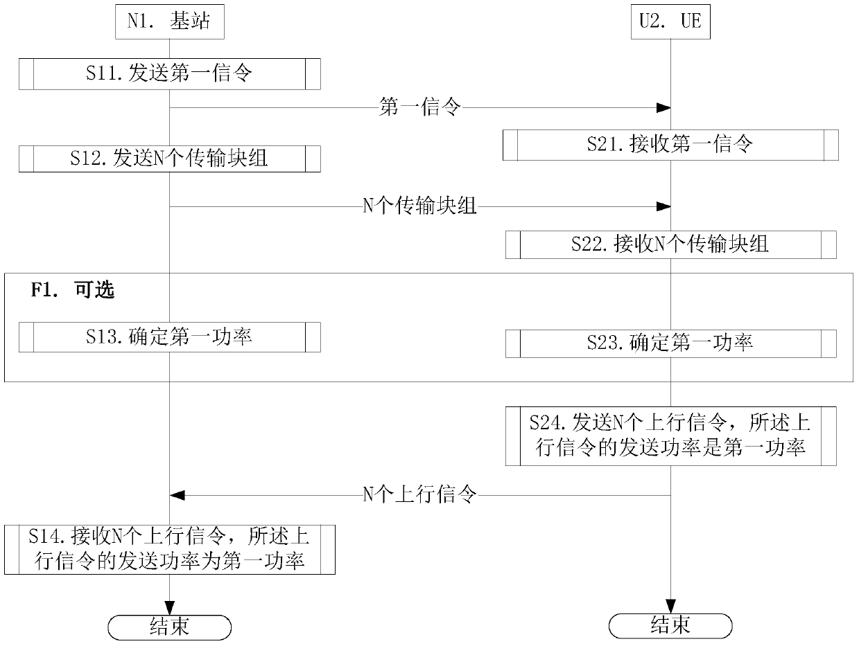
[0126] Embodiment 1 illustrates the flow chart of downlink transmission, as attached figure 1 shown. attached figure 1 In , the base station N1 is the maintenance base station of the serving cell of the UE U2, and the steps identified in the block F1 are optional steps.
[0127] for base station N1 , in step S11, the first signaling is sent, and the first signaling schedules the sending of N transport block groups. In step S12, N transport block groups are sent, and the N transport block groups are respectively sent in N LTE time slots. In step S13, it is determined that the sending power of the N uplink signaling is the first power. In step S14, N uplink signalings are respectively received in the N sub-resource groups, and the N uplink signalings respectively indicate whether the transport blocks in the N transport block groups are received correctly.
[0128] for UE U2 , receiving the first signaling in step S21. N transport block groups are received in step S22. ...
Embodiment 2
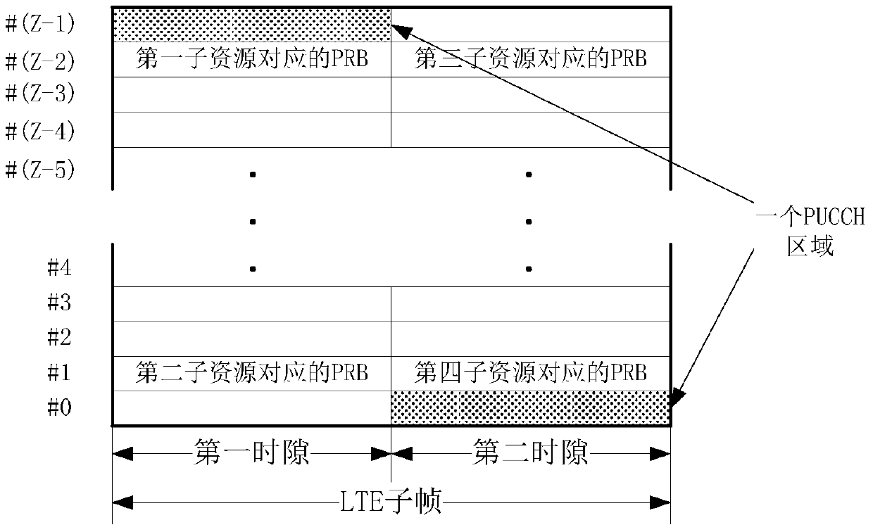
[0144] Embodiment 2 illustrates a schematic diagram of uplink signaling located in the PUCCH region, as shown in the attached figure 2 shown. attached figure 2 In , the grid filled with black dots identifies two PRBs that form a PUCCH region, the two PRBs are respectively located at the two frequency band boundaries of the current system bandwidth, and the two PRBs are respectively located at the first hour of an LTE subframe slot and the second slot. Indexes of Z PRB pairs in the current system bandwidth are integers from 0 to Z−1.
[0145] In Embodiment 2, the N in the present invention is 2, the J is 1, and the N LTE time slots are located in one LTE subframe.
[0146] As a sub-embodiment 1 of the second embodiment, the base station sends the second signaling to the UE, where the second signaling indicates L candidate resources, where L is 2. Wherein, the first signaling indicates the index of the first selected resource in the L candidate resources, the first selecte...
Embodiment 3
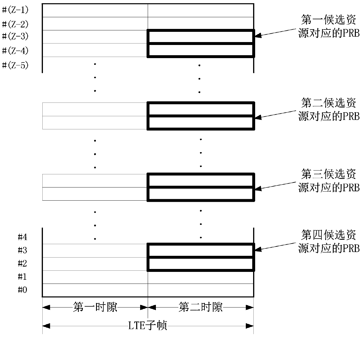
[0153] Embodiment 3 illustrates that the given format is a schematic diagram of the third format, as attached image 3 shown. attached image 3 In , the square marked by the thick line is the PRB corresponding to the candidate resource,
[0154] In Embodiment 3, the N in the present invention is 1, the J is 2, and the given format is the third format. The base station sends second signaling to the UE, where the second signaling indicates L candidate resources, where L is 2. Wherein, the first signaling indicates the index of the first selected resource in the L candidate resources, the first selected resource is composed of the N sub-resource groups in the present invention, and the second signaling is high-level signaling, so The L candidate resources include {the first candidate resource, the second candidate resource, the third candidate resource, and the fourth candidate resource}.
[0155] In Embodiment 3, one candidate resource includes 2 sub-resources, and the 2 sub...
PUM
 Abstract
Description
Claims
Application Information
 - R&D
- Intellectual Property
- Life Sciences
- Materials
- Tech Scout
- Unparalleled Data Quality
- Higher Quality Content
- 60% Fewer Hallucinations
Browse by: Latest US Patents, China's latest patents, Technical Efficacy Thesaurus, Application Domain, Technology Topic, Popular Technical Reports.
© 2025 PatSnap. All rights reserved.Legal|Privacy policy|Modern Slavery Act Transparency Statement|Sitemap|About US| Contact US: help@patsnap.com


