Electric rice cooker and cooking control method thereof
A technology of electric rice cooker and cooker body, which is applied in pressure cooker and other directions, and can solve the problems of affecting the taste of rice, inability to completely gelatinize, and hindering the uniform transfer of heat, etc.
- Summary
- Abstract
- Description
- Claims
- Application Information
AI Technical Summary
Problems solved by technology
Method used
Image

Examples
Embodiment 1
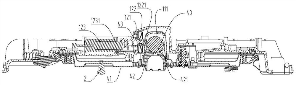
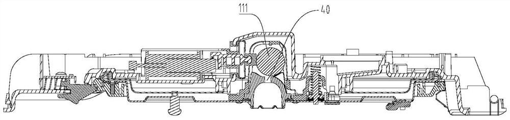
[0062] Such as figure 2 and image 3 As shown, the pressure limiting valve 11 is a sphere 111, the lid 4 has an arc-shaped slideway 421, the exhaust port 40 runs through the bottom end of the arc-shaped slideway 421, the sphere 111 is slidably arranged on the arc-shaped slideway 421 and Often abutting on the exhaust port 40 to close the exhaust port 40 , the pressure relief mechanism 12 can push the ball 111 to slide upward along the arc slideway 421 to open the exhaust port 40 . Such as figure 2 As shown, the pot cover 4 can include an outer cover and a cover plate 41, the cover plate 41 is arranged at the bottom of the outer cover, the pressure relief device 1 can be arranged between the outer cover and the cover plate 41, and the center of the cover plate 41 can have a through Mounting holes, support blocks 42 can be installed at the mounting holes, the arc-shaped slideway 421 is formed by the upper surface of the support block 42 being recessed downward, and the exhaus...
Embodiment 2
[0070] Such as Figure 4 and Figure 5 As shown, the structure of the present embodiment is substantially the same as that of the first embodiment, wherein the same components are designated with the same reference numerals, and the only difference is that the second embodiment uses a cam assembly instead of the electromagnet 123 in the first embodiment. Wherein, the cam component may be a motor 124 with a cam 1242 .
[0071] Specifically, refer to Figure 4 and Figure 5 , the pressure relief mechanism 12 includes: a motor 124 and a cam 1242, the motor 124 has an output shaft 1241, the cam 1242 is installed on the output shaft 1241 to be driven to rotate by the motor 124, the linkage 121 is located between the cam 1242 and the sphere 111, and the motor 124 During the rotation of the driving cam 1242, the outer peripheral surface of the cam 1242 can push the right end surface of the linkage 121 to make the linkage 121 translate in the left and right direction. 121 contact ...
Embodiment 3
[0074] Such as Figure 6 and Figure 7 As shown, the structure of the present embodiment is substantially the same as that of the first embodiment, wherein the same components use the same reference numerals, and the differences include: the magnetic valve 125 is used in the third embodiment to replace the electromagnet 123 in the first embodiment, And the movement direction of the ball 111 is the vertical direction.
[0075] Specifically, the sphere 111 is movable up and down above the exhaust port 40, the pressure relief mechanism 12 is a magnetic valve 125, and the pressure relief device 1 is configured such that when the magnetic valve 125 is energized, the magnetic valve 125 attracts the sphere 111 to move upward to open. Exhaust port 40. refer to Figure 6 and Figure 7 , the magnetic valve 125 can be set above the sphere 111, and the magnetic valve 125 can generate magnetic force to attract the metal material sphere 111 to move upward, thereby opening the exhaust po...
PUM
 Abstract
Description
Claims
Application Information
 - R&D
- Intellectual Property
- Life Sciences
- Materials
- Tech Scout
- Unparalleled Data Quality
- Higher Quality Content
- 60% Fewer Hallucinations
Browse by: Latest US Patents, China's latest patents, Technical Efficacy Thesaurus, Application Domain, Technology Topic, Popular Technical Reports.
© 2025 PatSnap. All rights reserved.Legal|Privacy policy|Modern Slavery Act Transparency Statement|Sitemap|About US| Contact US: help@patsnap.com