
Positioning punching die

A technology for positioning punches and molds, applied in metal processing, etc., can solve the problems of high labor intensity, inability to process automatically, and high risk of work-related injuries, and achieve the effects of improving efficiency, saving manpower and time

Inactive Publication Date: 2017-04-05
SHENZHEN MAKEN M & E
View PDF7 Cites 2 Cited by
  • Summary
  • Abstract
  • Description
  • Claims
  • Application Information

AI Technical Summary

Problems solved by technology

During the automatic punching process, the product is mainly transported by the suction cup. To transport the product on the lower die, the force of the suction cup must overcome the resistance of the positioning pin of the lower die, which requires a suction cup with a diameter of more than 6mm on the outside of the positioning pin; But in fact, about half of the products do not have enough space in the frame, so that it cannot be processed automatically
[0004] Therefore, the defect of this lower die positioning method leads to the fact that the current punching process still requires a lot of manpower, which not only has high labor intensity and high risk of work-related injuries, but also affects the overall benefit of the manufacturer.

Method used


Image

  • Positioning punching die
  • Positioning punching die

Examples


Embodiment 1

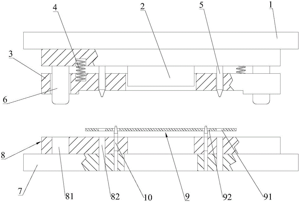
[0026] Please refer to figure 1 , Embodiment 1 of the present invention is: a positioning punching die for punching FPC products 9 . It includes an upper mold and a lower mold, and the lower mold is located below the upper mold. The FPC product 9 to be punched is provided with a first positioning hole 92 and a second positioning hole 91 . The first positioning hole 92 does not need to be dedicated, and the used positioning hole of the previous process can be used.

[0027] The upper mold includes an upper mold installation base plate 1, a punch 2 and an upper mold stripping plate 3, the punch 2 is fixed on the bottom of the upper mold installation base plate 1, and the upper mold stripping plate 3 is connected to the bottom of the punch 2 by a spring 4 connect. When in the original state, the bottom of the punch 2 is indented in the stripping plate 3 of the upper die, and when punching, the spring 4 is compressed, and the punch 2 stretches out of the stripping plate 3 of th...


PUM


Abstract

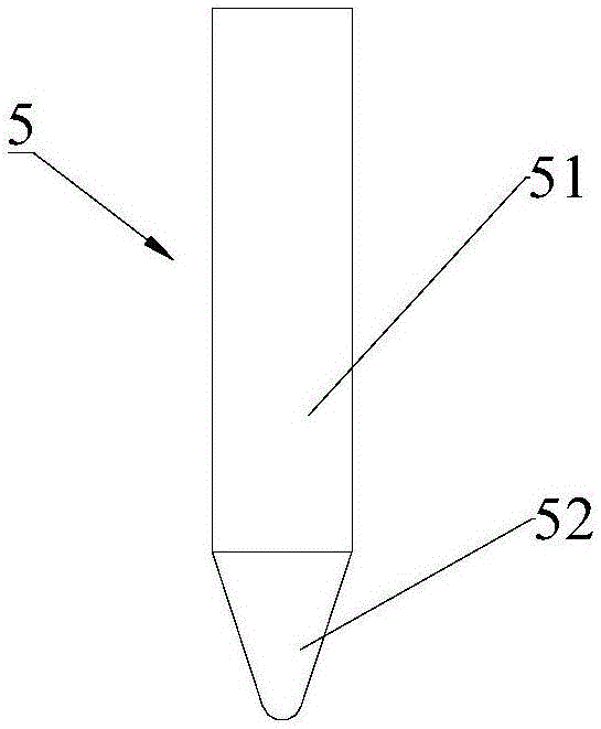
The invention discloses a positioning punching die which comprises an upper die and a lower die. The lower die is located below the upper die. The upper die comprises a male die and an upper die stripper plate. The upper die stripper plate is connected with the bottom of the male die through a spring. The upper die is provided with a second positioning pin. The lower die comprises a female die. The upper end of the female die is provided with a first positioning pin. Due to the fact that an upper die precise positioning way is adopted for the positioning punching die, the good punching quality can be ensured, meanwhile, after punching is completed, the elastic force of the spring and the gravity of the upper die stripper plate can provide a force for an FPC board to enable the FPC board to be smoothly disengaged from the second positioning pin so as to fall down to the lower die, accordingly, the resistance of the second positioning pin does not need to be overcome any more during board taking, automatic board taking can be achieved by adopting a small-size suction cup, labor and time can be saved, and benefits are improved.

Description

technical field [0001] The invention relates to the technical field of FPC positioning punching, in particular to a positioning punching die. Background technique [0002] In recent years, with the rapid development of smart phones, FPC, that is, flexible circuit boards, has developed rapidly. Especially with the concept of wearable devices being proposed and gradually accepted, FPC will usher in a new round of rapid development. Because the thickness of FPC is usually less than 0.5mm, there are particularities such as expansion and contraction in the production process, the molding method in mass production usually adopts the method of die punching, that is, a plurality of positioning holes are arranged around an FPC unit, and the positioning holes are placed on the mold. Dowel pins, followed by punching. The current positioning method is to use the lower mold for positioning. This positioning method requires accurate positioning, so the difference between the positioning ...

Claims


Application Information

Patent Timeline
Patent Type & Authority Applications(China)
IPC IPC(8): B26F1/44
CPCB26F1/44
Inventor 史洪智
Owner SHENZHEN MAKEN M & E
Learn More