Loading and unloading clamping fixture for punching machine

A clamping and punching technology, used in feeding devices, manufacturing tools, positioning devices, etc., can solve the problems of low safety factor, low placement efficiency, easy to cause injuries, etc., to achieve fast placement, reduce enterprise costs, and improve processing. The effect of efficiency

Inactive Publication Date: 2012-07-04
昆山艾博机器人股份有限公司
View PDF7 Cites 1 Cited by
  • Summary
  • Abstract
  • Description
  • Claims
  • Application Information

AI Technical Summary

Problems solved by technology

[0003] In order to solve the problems of low efficiency, slow speed, poor precision, low safety factor, and easy injury accidents caused by manual placement of parts to be punched by punching machines in the prior art, the present invention provides a simple structure and high safety factor. , which can quickly and accurately place the punching and loading fixtures on the punching machine

Method used


Image

  • Loading and unloading clamping fixture for punching machine
  • Loading and unloading clamping fixture for punching machine
  • Loading and unloading clamping fixture for punching machine

Examples


Embodiment Construction

[0016] The present invention will be further described below in conjunction with the accompanying drawings.

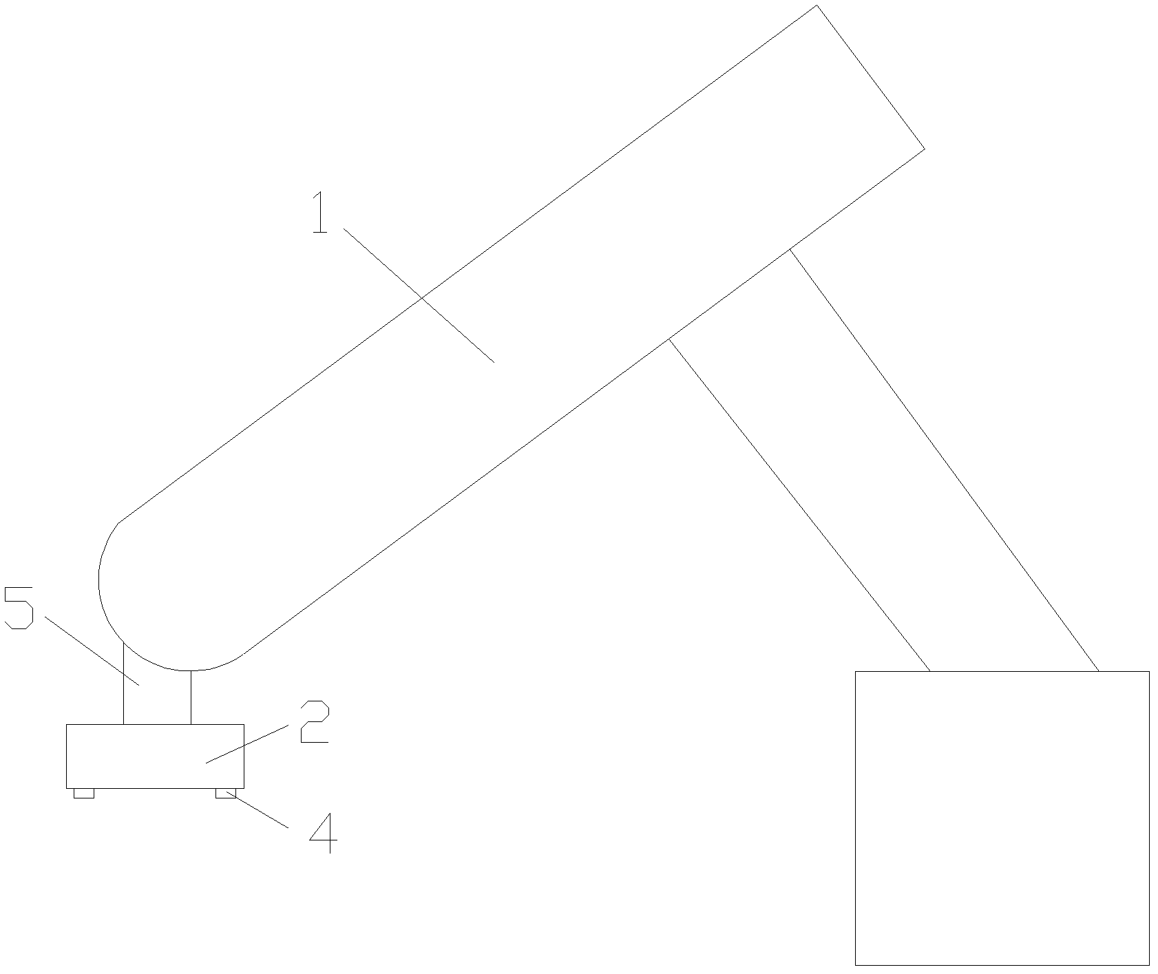
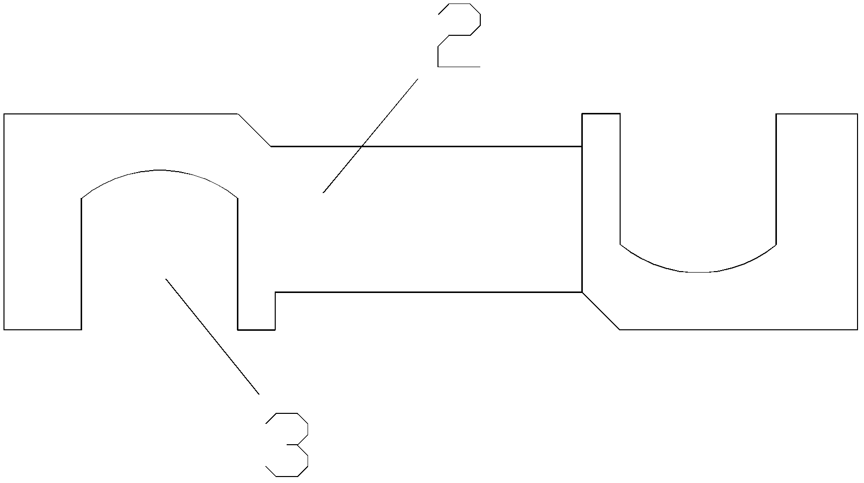
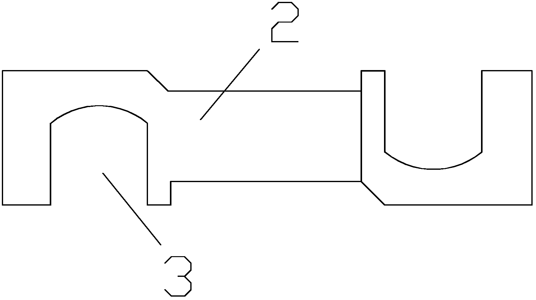
[0017] like Figure 1-2 As shown, a clamping fixture for loading and unloading on a punching machine includes a manipulator 1 and a clamp plate 2. U-shaped openings 3 are respectively provided at both ends of the clamp plate 2, and the two U-shaped openings 3 are arranged in opposite directions. The upper middle part of the fixture plate 2 is connected with the control arm 5 of the manipulator 1 , and vacuum suction cups 4 are symmetrically arranged on both sides below the fixture board 2 , and the vacuum suction cups 4 are connected with the vacuum generator.

[0018] There are two uprights beside the punching machine, one upright is used to place the parts to be punched, the other is used to place the punched parts, and the placement height of the parts to be punched is higher than the placement height of the punched parts. The vacuum generator is turned on, and the...


PUM


Abstract

The invention discloses a loading and unloading clamping fixture for a punching machine, which comprises a fixture plate, and is characterized by further comprising a manipulator, and two reverse U-shaped openings are arranged at two ends of the fixture plate respectively. The upper middle of the fixture plate is connected with a control arm of the manipulator, and vacuum chucks are arranged on two lower sides of the fixture plate respectively and connected with a vacuum generator. The loading and unloading clamping fixture for the punching machine solves the problems of low placement efficiency, low speed, poor precision, low safety factor and easiness in causing injury accidents of a punching machine in the prior art adopting manual displacement of parts to be punched, and is simple in structure, high in safety factor and capable of rapidly and accurately placing parts to be punched.

Description

technical field [0001] The invention relates to a clamping fixture, in particular to a punching machine unloading and clamping fixture. Background technique [0002] A punch is a punching press. Compared with traditional mechanical processing, the stamping process has the advantages of saving materials and energy, high efficiency, low technical requirements for operators, and products that cannot be achieved by mechanical processing through various mold applications, so its use is becoming more and more. more extensive. However, at present, the workpieces to be punched are placed on the working table of the punching machine, and they are mostly placed manually. There are the following problems: 1. Manually placing the workpieces to be punched, the placement efficiency is low, the speed is slow, and the punching speed of the punching machine cannot be satisfied, which affects the processing efficiency of the entire punching machine. . 2. Manually place the parts to be punc...

Claims


Application Information

Patent Timeline
Patent Type & Authority Applications(China)
IPC IPC(8): B21D43/10
Inventor 邹兴怀
Owner 昆山艾博机器人股份有限公司
Why Eureka
Try Eureka