Feed mechanism

A feeding mechanism and feeding technology, which are applied to conveyor objects, transportation and packaging, etc., can solve problems such as large position deviation, slow bar workpiece speed, and affecting production efficiency.

Active Publication Date: 2017-02-01
GUANGXI BINYANG TIANXIANG ELECTRONICS
View PDF7 Cites 1 Cited by
  • Summary
  • Abstract
  • Description
  • Claims
  • Application Information

AI Technical Summary

Problems solved by technology

[0002] At present, when the production workshop transports the rod workpieces of electronic accessories, the rod workpieces are placed manually. There are two small round holes at the bottom of the rod workpieces. When placing the rod workpieces, the two round holes need to be snapped into the transport mechanism. On the two circular protrusions, due to the small diameter of the round hole, the speed of placing the rod workpiece by hand is slow, the position of the rod workpiece is inaccurate, and the position deviation is large, resulting in serious problems in the post-process processing, often stuck and shut down. Seriously affect production efficiency

Method used


Image

  • Feed mechanism
  • Feed mechanism
  • Feed mechanism

Examples


Embodiment Construction

[0017] The present invention will be described in detail below in conjunction with the accompanying drawings and embodiments.

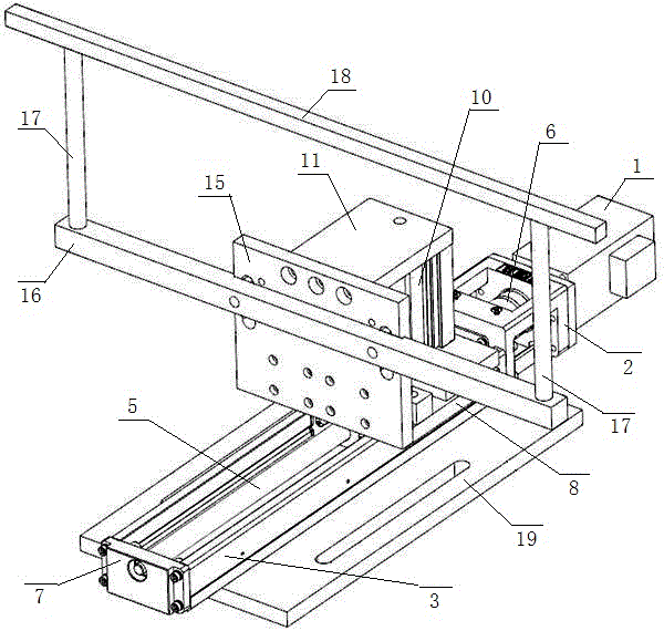
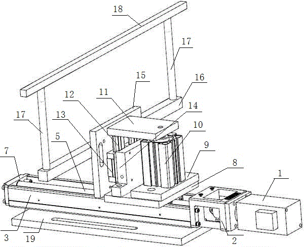
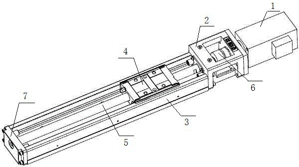
[0018] Such as Figure 1 to Figure 7 As shown, a feeding mechanism includes a horizontal motion mechanism, a vertical motion mechanism, a workpiece clamping mechanism and a base plate 19, and the horizontal motion plate is fixed on the base plate 19; the horizontal motion mechanism includes a servo motor 1, a motor frame 2, and a chute 3 , threaded slider 4, threaded rod 5, coupling 6, chute end plate 7 and horizontal movement plate 8, one end of chute 3 is connected to motor frame 2, the other end is closed by chute end plate 7, motor frame 2 The servo motor 1 is fixed, one end of the threaded rod 5 is rotated and positioned on the chute end plate 7, the other end passes through the front panel of the motor frame 2 and is connected with the servo motor 1 through a coupling 6, the threaded slider 4 is connected with the belt The threaded rod 5 is th...


PUM


Abstract

The invention relates to a feed mechanism which comprises a horizontal movement mechanism, a vertical movement mechanism, a workpiece clamping mechanism and a bottom plate. The horizontal movement mechanism comprises a servo motor, a motor rack, a sliding groove, a sliding block with a thread, a rod with a thread, a coupling, a sliding groove end plate and a horizontal movement plate. The vertical movement mechanism comprises an air cylinder base plate, an up-down air cylinder, an up-down air cylinder plate, a guide rail strip, sliding blocks with grooves, a guide rail strip seat and a vertical movement plate. The workpiece clamping mechanism comprises a feed bar seat and magnet bars. According to the feed mechanism, the horizontal movement mechanism can be used for driving the vertical movement mechanism and the workpiece clamping mechanism to do horizontal linear movement, the vertical movement mechanism can be used for driving the workpiece clamping mechanism to do vertical movement, and the workpiece clamping mechanism can be used for clamping a bar workpiece; the defects of manual operation are avoided; the placement speed is high; the placement positions are accurate; the frequency of jamming and shutdown is effectively reduced; and the production efficiency is effectively improved.

Description

technical field [0001] The invention relates to the technical field of electronic production, in particular to a feeding mechanism. Background technique [0002] At present, when the production workshop transports the rod workpieces of electronic accessories, the rod workpieces are placed manually. There are two small round holes at the bottom of the rod workpieces. When placing the rod workpieces, the two round holes need to be snapped into the transport mechanism. On the two circular protrusions, due to the small diameter of the round hole, the speed of placing the rod workpiece by hand is slow, the position of the rod workpiece is inaccurate, and the position deviation is large, resulting in serious problems in the post-process processing, often stuck and shut down. Seriously affect production efficiency. [0003] Therefore, it is necessary to design a feeding mechanism that can effectively replace the rod workpiece placed by hand, has fast placement speed, accurate plac...

Claims


Application Information

Patent Timeline
Patent Type & Authority Applications(China)
IPC IPC(8): B65G47/90
CPCB65G47/901
Inventor 蔡旌章
Owner GUANGXI BINYANG TIANXIANG ELECTRONICS
Why Eureka
Try Eureka