Battery pack installation structure of rear vibration-isolated pure electric logistics vehicle

A pure electric animal and installation structure technology, applied in the direction of electric power devices, transportation and packaging, shock absorbers, etc., can solve the problem of vibration isolation effect of the battery pack turned forward, and achieve good vibration isolation and energy absorption effect and reasonable utilization Effect

Active Publication Date: 2018-09-21
杭州衡源汽车科技有限公司
View PDF9 Cites 0 Cited by
  • Summary
  • Abstract
  • Description
  • Claims
  • Application Information

AI Technical Summary

Problems solved by technology

[0004] The invention provides a battery pack installation structure of a rear-mounted vibration-isolation type pure electric logistics vehicle that can prevent the battery pack from turning forward during a collision and has a good vibration isolation effect, and solves the problem of the existing rear-mounted automobile battery pack installation structure. When there is a collision, the battery pack is prone to flipping forward and the vibration isolation effect is poor

Method used


Image

  • Battery pack installation structure of rear vibration-isolated pure electric logistics vehicle
  • Battery pack installation structure of rear vibration-isolated pure electric logistics vehicle
  • Battery pack installation structure of rear vibration-isolated pure electric logistics vehicle

Examples


Embodiment 1

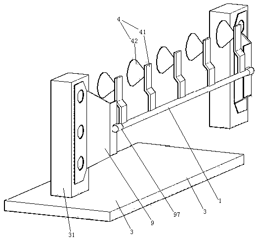
[0040] Embodiment one, see figure 1 , a battery pack installation structure of a rear-mounted vibration-isolation pure electric logistics vehicle, including a car floor 3 and a front bumper 1.

[0041] The car floor 3 is positioned between the front of the trunk behind the car and the rear of the rear seat during use. Both sides of the automobile floor 3 are provided with a connecting column 31 .

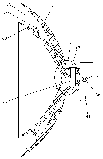
[0042] The front bumper 1 is a tubular structure, specifically a stainless steel tube. The front bumper 1 extends in the width direction of the vehicle. Front bumper 1 is positioned at the rear of the rear row seat of automobile. The front bumper 1 is connected with five battery pack fixing mechanisms 4 . The five battery pack fixing mechanisms 4 are distributed along the length direction of the front bumper 1 , that is, the width direction of the vehicle. The battery pack fixing mechanism 4 includes a connection base 41 and a first suction cup 42 connected to the rear side of t...

Embodiment 2

[0054] Embodiment two, the difference with embodiment one is:

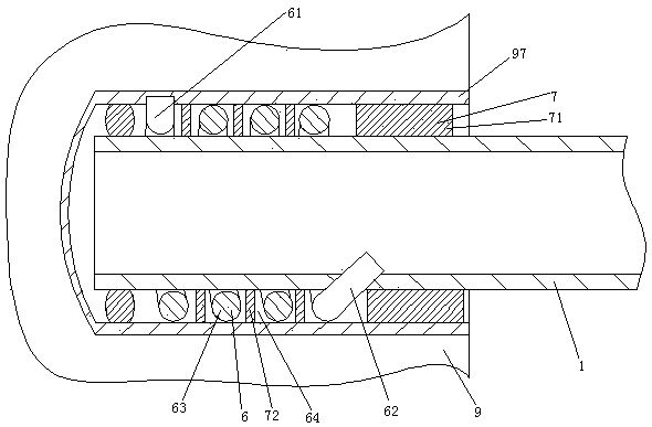
[0055] see Figure 9 , the connecting frame 90 is connected with the heat preservation mechanism 10 . The connecting frame 90 also includes a connecting rod 98 and a damping rod 9 . The connecting rod 98 is an arc-shaped structure that arches upwards (of course, downwards is also possible). One end of the connecting rod 98 is connected with the connecting column 31 . The other end of the connecting rod 98 is connected with one end of the damping rod 9 . The other end sleeve 97 of the damping rod 9 is connected together.

[0056] The heat preservation mechanism 10 includes a box body 100 , a swing rod 107 and a driving motor 108 . The box body 100 is connected with the connecting column 31 . The swing rod 107 is provided with a coating head 1071 . The applicator head 1071 is ring-shaped. The coating head 1071 is sheathed on the connecting rod 98 . The driving motor 108 is fixed on the box body 100 .

[00...


PUM


Abstract

The invention relates to the technical field of manufacturing of new energy vehicles. A rear vibration isolation type battery pack installation structure of a pure electric logistic vehicle comprises a front stop lever and a vehicle floor located between a trunk and a back seat, wherein the front stop lever is of a tubular structure and extends in the width direction of the vehicle; the front stop lever is provided with a plurality of battery pack fixing mechanisms distributed in the length direction of the front stop lever; each battery pack fixing mechanism comprises a connection base connected with the front stop lever, a first suction disc connected with the rear side of the connection base, and a second suction disc located inside the first suction disc, and an adsorption groove is defined between the first suction disc and the second suction disc; the two ends of the front stop lever are both connected with a connection frame; and the connection frame is connected with the vehicle floor together. The rear vibration isolation type battery pack installation structure of the pure electric logistic vehicle has the advantages of preventing battery packs from turning over forwards during collision and being good in vibration isolation effect, and the problems that as for an existing rear vehicle battery pack installation structure, the battery packs easily turn over forwards and the vibration isolation effect is poor in case of collisions are solved.

Description

technical field [0001] The invention relates to the technical field of new energy automobile manufacturing, in particular to a battery pack installation structure of a rear-mounted vibration-isolation pure electric logistics vehicle. Background technique [0002] The pure electric logistics vehicle in the electric vehicle will be provided with a battery pack for driving the motor, and the battery pack is installed in the body of the car through the battery pack installation structure. The installation structure of the battery pack is divided into two ways: front and rear according to the position installed on the vehicle body. In the patent document with the Chinese patent number 201220611004X, the authorized publication date being May 29, 2013, and the patent document titled "An Integrated Battery Pack Installation Structure", a front-mounted battery pack installation structure is disclosed, namely The battery pack is installed in the cabin of the car. In the Chinese pate...

Claims


Application Information

Patent Timeline
Patent Type & Authority Patents(China)
IPC IPC(8): B60K1/04F16F13/00F16F9/504
CPCB60K1/04B60K2001/0416F16F9/504F16F13/007
Inventor 王祖光王艳
Owner 杭州衡源汽车科技有限公司
Why Eureka
Try Eureka