Hydraulically controlled pivot type water injection pump capable of achieving automatic hydraulic pressure adjustment

A hydraulic automatic and pilot-operated technology, applied in variable capacity pump components, liquid fuel engines, liquid variable capacity machines, etc., can solve problems such as increased power consumption, insufficient system pressure, energy waste, etc., to reduce input pressure Poor requirements, solve incomplete commutation, improve the effect of application range

Active Publication Date: 2017-04-05
CHINA PETROLEUM & CHEM CORP +1
View PDF8 Cites 3 Cited by
  • Summary
  • Abstract
  • Description
  • Claims
  • Application Information

AI Technical Summary

Problems solved by technology

At present, the water injection stations in use in oil fields generally adopt a set of pressure systems, resulting in low-pressure water injection wells throttling and controlling water injection, and high-pressure water injection wells due to insufficient system pressure resulting in under-injection or no water absorption.
In order to meet the water injection requirements of high-pressure wells, oilfields usually adopt two methods: overall pressure boost and local electric boost. Electric about 11 x 10 4 Kw.h, high operating energy consumption
From the perspective of the entire water injection system, on the one hand, the booster pump increases the additional power consumption to pressurize the water injection; on the other hand, the pressure of the low-pressure well is too high to control the water injection, resulting in a huge valve control loss, and the throttling loss rate is as high as 16.7%. cause a lot of energy waste

Method used


Image

  • Hydraulically controlled pivot type water injection pump capable of achieving automatic hydraulic pressure adjustment

Examples


Embodiment Construction

[0018] The detailed description and technical content of the present invention are described below with the accompanying drawings, but the accompanying drawings are only provided for reference and description, and are not intended to limit the present invention.

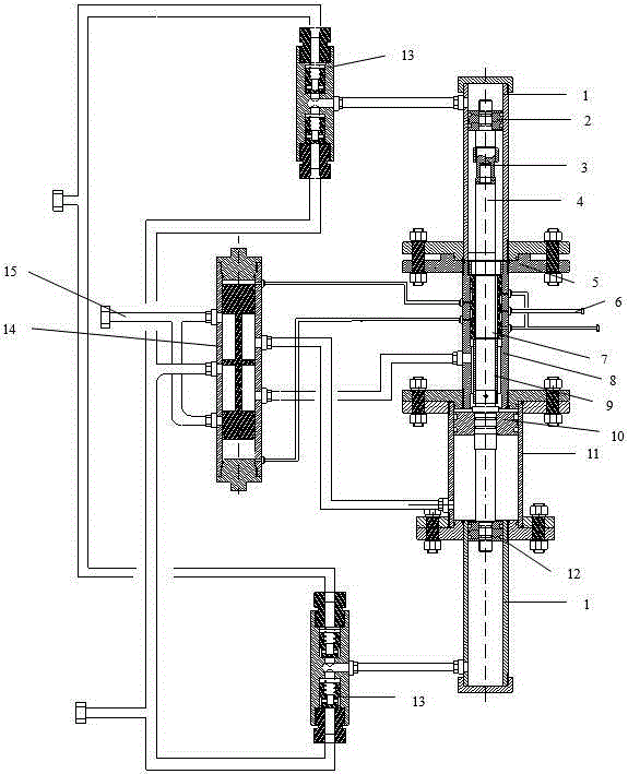
[0019] according to figure 1 , the hydraulic control pilot hydraulic automatic pressure-regulating water injection pump, including the front booster cylinder, reversing working cylinder 8, low-pressure working cylinder 11, and rear booster cylinder connected sequentially from front to back. All the above cylinders pass through their respective manifolds. Connected to the main reversing valve 14, the reversing working cylinder is also connected to the pilot valve control manifold 6, and the pilot valve control manifold is connected to the main reversing valve 14, and the main reversing valve also passes its own high and low pressure The outlet is connected with the high and low pressure manifold 15. A front one-way v...


PUM


Abstract

The invention discloses a hydraulically controlled pivot type water injection pump capable of achieving automatic hydraulic pressure adjustment. The water injection pump comprises a front pressurization cylinder, a reversing working cylinder, a low pressure working cylinder and a back pressurization cylinder which are sequentially connected from front to back, wherein the front pressurization cylinder, the reversing working cylinder, the low pressure working cylinder and the back pressurization cylinder are connected to a main reversing valve through respective manifolds; the reversing working cylinder is connected with a pivot valve control manifold; the pivot valve control manifold is connected with the main reversing valve; the main reversing valve is further connected with a high-low pressure manifold through a self high-low pressure outlet; a front check valve group is arranged on the manifold connected between the front pressurization cylinder and the main reversing valve; a back check valve group is arranged on the manifold connected between the back pressurization cylinder and the main reversing valve; and the front check valve group communicates with the back check valve group. According to the water injection pump, surplus energy of a low pressure injection well is converted into energy required by pressurization injection of a high pressure injection well, energy does not need to be additionally added, water injection pressure of the high pressure well and the low pressure well is re-distributed according to needs, the injection pressure requirements of the high pressure well and the low pressure well are met, and the water injection pump has important meaning for decreasing the number of insufficient injection wells and improving the energy-saving effect of a water injection system.

Description

technical field [0001] The invention relates to an oil field water injection pump, in particular to a hydraulic control pilot hydraulic automatic pressure regulating water injection pump. Background technique [0002] Water injection development is the main development method adopted by oilfields. The water injection pressure of different oil layers or different water injection wells is different due to the physical properties of the reservoir itself and the plugging damage in the later stage. At present, the water injection stations in use in oil fields generally adopt a set of pressure systems, resulting in low-pressure water injection wells throttling and controlling water injection, and high-pressure water injection wells lacking injection or not absorbing water due to insufficient system pressure. In order to meet the water injection requirements of high-pressure wells, oilfields usually adopt two methods: overall pressure boost and local electric boost. Electric about...

Claims


Application Information

Patent Timeline
IPC IPC(8): F04B49/22F04B53/10F04B9/129
Inventor 王增林崔玉海罗杨马珍福孙金峰王磊渠慧敏咸国旗谭云贤戴群韦良霞
Owner CHINA PETROLEUM & CHEM CORP
Why Eureka
Try Eureka