Multiple-input multiple-output space light communication system and method

A space optical communication, multi-transmit and multi-receive technology, applied in the field of optical communication, can solve the problems of restricting the timeliness and stability of the communication system, cannot meet the high-speed data transmission, and the communication data receiving ability is weak, so as to improve the information capacity and total power , Improve the receiving ability, expand the effect of field of view

Inactive Publication Date: 2017-04-05
INST OF SEMICONDUCTORS - CHINESE ACAD OF SCI +1
View PDF5 Cites 7 Cited by
  • Summary
  • Abstract
  • Description
  • Claims
  • Application Information

AI Technical Summary

Problems solved by technology

[0002] For space optical communication systems, whether it is the transmission between the three platforms of sea, land and air, between satellites and the earth, or between satellites, optical signals are transmitted over long distances, due to the effects of atmospheric turbulence and beam diffusion. Both seriously restrict the timeliness and stability of the communication system
Existing space optical communication often adopts the method of single-channel transmission and single-channel reception. With the explosive development of the demand for communication capacity expansion,

Method used


Image

  • Multiple-input multiple-output space light communication system and method
  • Multiple-input multiple-output space light communication system and method
  • Multiple-input multiple-output space light communication system and method

Examples


Embodiment Construction

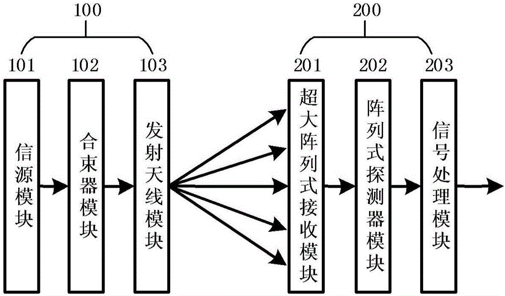
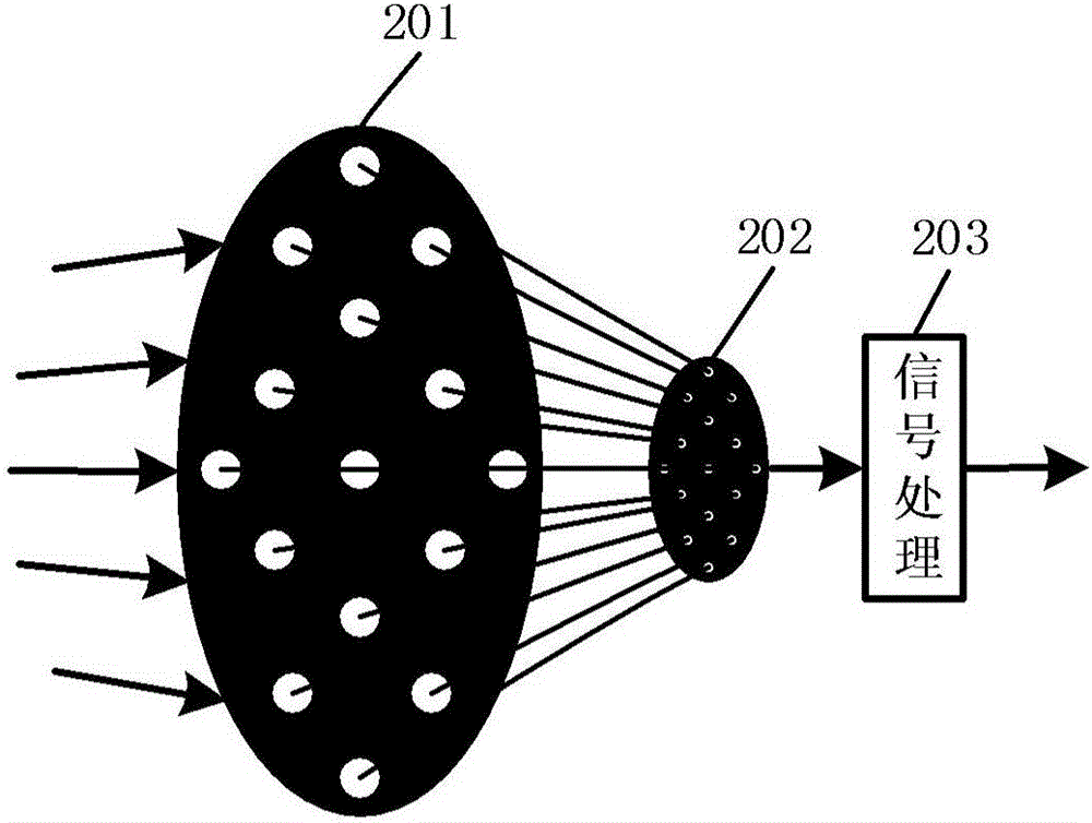
[0023] see Figure 1-Figure 3 As shown, the present invention provides a multi-transmit and multi-receive spatial optical communication system, including a transmitting end 100 and a receiving end 200 connected thereto ( figure 1 in), where:

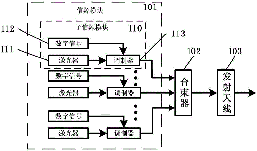
[0024] The transmitting end 100 includes a signal source module 101 , a beam combiner module 102 and a transmitting antenna module 103 connected in sequence. The signal source module 101 is used to output the signal light of n channels of digital signals modulated on optical carriers of different wavelengths, n is an integer greater than or equal to 2; the beam combiner module 102 is a low-loss multi-channel optical coupling device, which can It is a multi-inlet and single-outlet optical coupling device that couples signal lights of different optical wavelengths into a beam of light. The transmitting antenna module 103 is an optical lens group with the function of collimating beams, which is used to transmit the collimated output of th...


PUM


Abstract

A multiple-input multiple-output space light communication system comprises an emission terminal and a receiving terminal connected with the emission terminal. The emission terminal includes an information source module, a beam combiner module and an emission antenna module; the receiving module includes an extra-large array receiving module, an array detector module and a signal processing module; the beam combiner module is configured to perform beam combination of n-way signals outputted by the information source module and output one-way signal light; the emission module is configured to emit the signal light outputted by the beam combiner and transmit the signal light to the receiving terminal in the space long-distance transmission mode; the extra-large array receiving module is configured to receive the n-way signal light emitted by the emission terminal, and each optical lens in the extra-large array receiving module collects the signal light to a detector at the back; the array detector module is configured to perform photovoltaic conversion of the received signal light and output electric signals; and the signal processing module is configured to process and output digital signals.

Description

technical field [0001] The invention belongs to the technical field of optical communication, and in particular relates to a multi-transmit and multi-receive space optical communication system and a communication method. Background technique [0002] For space optical communication systems, whether it is the transmission between the three platforms of sea, land and air, between satellites and the earth, or between satellites, optical signals are transmitted over long distances, due to the effects of atmospheric turbulence and beam diffusion. Both seriously restrict the timeliness and stability of the communication system. Existing space optical communication often adopts the method of single-channel transmission and single-channel reception. With the explosive development of the demand for communication capacity expansion, this method can no longer meet the requirements of high-speed data transmission. It is necessary to improve the existing space optical communication syste...

Claims


Application Information

Patent Timeline
IPC IPC(8): H04B10/11H04B10/50H04B10/60
CPCH04B10/11H04B10/506H04B10/60
Inventor 刘大畅刘建国祝宁华
Owner INST OF SEMICONDUCTORS - CHINESE ACAD OF SCI
Why Eureka
Try Eureka