Breather valve used for breathing machines

A technology of breathing valve and ventilator, applied in the field of ventilator, can solve the problem of incapability of universal use of ventilator, and achieve the effect of improving the scope of application and work efficiency

Active Publication Date: 2017-04-19
河北谊安奥美医疗设备有限公司
View PDF4 Cites 7 Cited by
  • Summary
  • Abstract
  • Description
  • Claims
  • Application Information

AI Technical Summary

Problems solved by technology

[0003] The purpose of the present invention is to solve the technical problem that the existing breathing valve cannot be used universally on all ventilators du

Method used


Image

  • Breather valve used for breathing machines
  • Breather valve used for breathing machines
  • Breather valve used for breathing machines

Examples


Embodiment 1

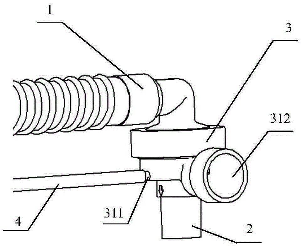
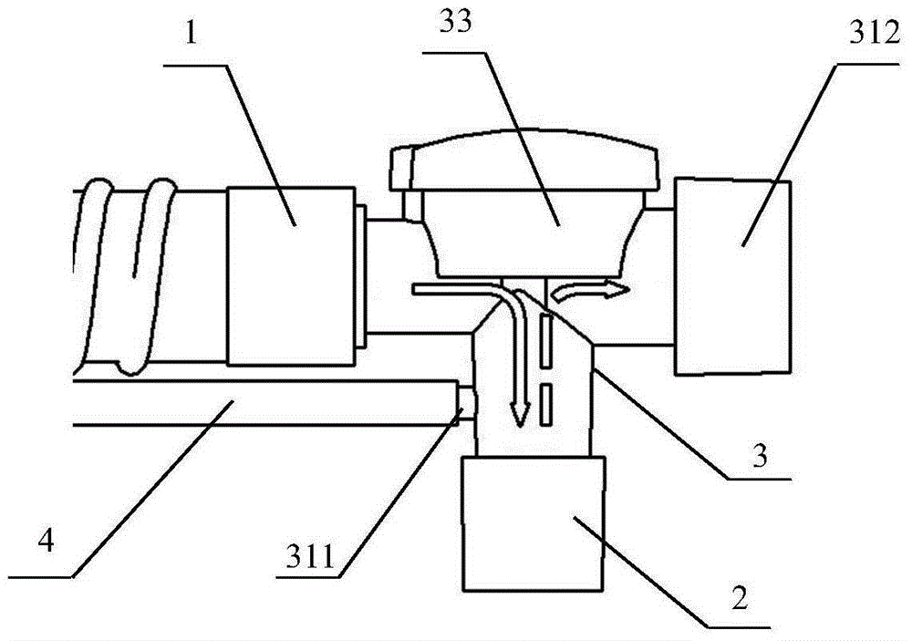
[0042] Breathing valve based on the above structure, such as Figure 5 , 6 The shown breathing valve equipped with a mechanical PEEP valve specifically includes: an inhalation pipeline interface 315, a patient end interface 2, a pressure sampling port 311, a valve port 319 and a dual-purpose interface 314; the inhalation pipeline interface 315 , the patient end interface 2, the pressure sampling port 311, the valve port 319 and the dual-purpose interface 314 communicate with each other through the first cavity 316 provided at the center of the breathing valve; the dual-purpose interface 314 is connected to the mechanical PEEP valve, And the valve port 319 is connected with the valve cover 33 matched with the mechanical PEEP valve.

[0043] like Figure 5 As shown, the radial section of the suction pipeline interface 315 is covered with a first one-way diaphragm 34, and the first one-way diaphragm 34 is installed on the band pass provided at the end of the suction pipeline in...

Embodiment 2

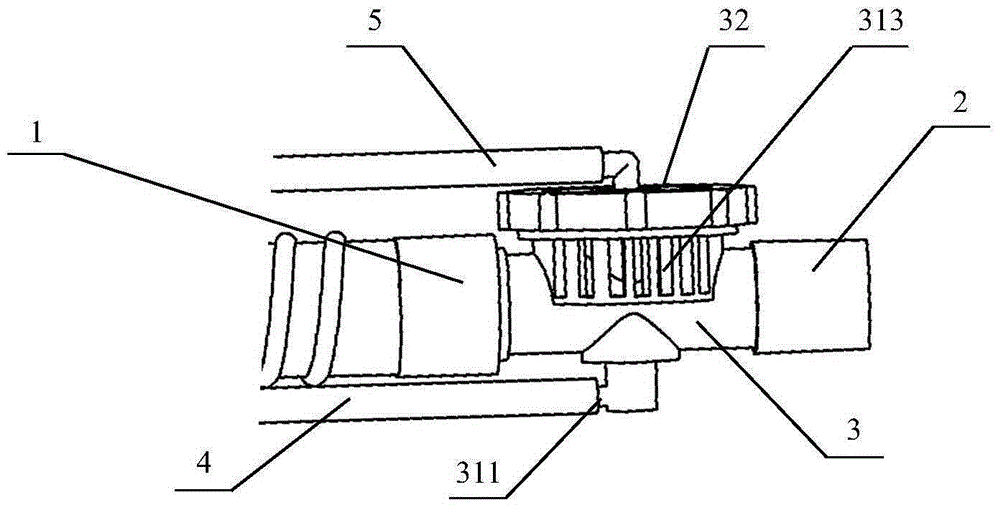
[0053] When using with electronic PEEP valve, refer to Figure 7 , 8 As shown in the breathing valve, the valve cover 32 matched with the electronic PEEP valve is used together with the valve body 31. The dual-purpose interface 314 is not connected to other equipment and is only used as an exhalation port. If the main unit of the ventilator used has a one-way gas check diaphragm, then Figure 5 The first one-way diaphragm 34 shown in may not be installed as an option. Structurally, the breathing valve of this embodiment differs from the breathing valve described in Embodiment 1 in that: the valve cover 32 matched with the electronic PEEP valve is no longer provided with an annular groove, and the valve cover matched with the electronic PEEP valve is directly used 32 press the edge of the expiratory diaphragm 35 to seal the circular hole 351 on the expiratory diaphragm 35. In this use state, the control air channel 318 on the valve body 31 and the circular hole on the expirat...


PUM


Abstract

The invention provides a breather valve used for breathing machines. The breather valve comprises an inspiration pipeline connector (315), a patient end connector (2), a pressure sampling port (311), a valve port (319) and a dual-purpose connector (314), wherein the dual-purpose connector (314) is connected with a mechanical PEEP valve, and the valve port (319) is connected with a valve cover (33) matched with the mechanical PEEP valve, or the dual-purpose connector (314) is directly used as an expiration port, and the valve port (319) is connected with a valve cover (32) matched with an electronic PEEP valve. The breather valve disclosed by the invention is provided with the dual-purpose connector, so that the mechanical PEEP valve and the electronic PEEP valve can be both matched in use; only the valve covers, matched with the corresponding PEEP valves, are needed to be replaced for realizing switching of the mechanical PEEP valve and the electronic PEEP valve; and therefore, universality of different breathing machines can be realized, so that the applicable range and the working efficiency of the breather valve are improved.

Description

technical field [0001] The invention relates to the technical field of ventilators, in particular to a breathing valve for a ventilator. Background technique [0002] At present, there are two main ways for ventilators to control PEEP. One is to control the PEEP valve externally on the exhalation port of the breathing valve. Its typical structure is as follows: figure 1 , figure 2 As shown, the mechanical PEEP valve is installed at the mechanical PEEP interface 312 on the breathing valve 3, and the valve cover 33 matched with the mechanical PEEP valve is installed on the top of the breathing valve 3 for the patient to exhale; The pressured airflow provided by the built-in electronic PEEP valve of the host is controlled by software, and different pressures of control air are given to maintain the corresponding PEEP value. Its typical structure is as follows: image 3 As shown, the valve cover 32 matched with the electronic PEEP valve is installed on the breathing valve 3 ,...

Claims


Application Information

Patent Timeline
IPC IPC(8): A61M16/20
CPCA61M16/0816A61M16/0858A61M16/205A61M16/206A61M16/208
Inventor 马颖丹申佑方
Owner 河北谊安奥美医疗设备有限公司
Why Eureka
Try Eureka