
An electric reciprocating cutting device

A cutting device and reciprocating technology, which is applied in metal processing and other directions, can solve the problems of depending on the operator for effect control, deviation of pruning consistency, and uneven hair length, etc., so as to improve fluency, reduce interference, and have good functional integration Effect

Inactive Publication Date: 2018-06-19
牟丹
View PDF10 Cites 0 Cited by
  • Summary
  • Abstract
  • Description
  • Claims
  • Application Information

AI Technical Summary

Problems solved by technology

[0002] At present, people's trimming of long hair (such as hair, etc.) is mainly done by manual shears (such as scissors). Cutting hair with manual shears is not only inefficient, but also poor in quality. Some people also use electric clippers to trim, However, the cutting range of current electric clippers is small, and the trimming consistency is inconsistent. The effect control is completely dependent on the operator, and it is easy to have uneven hair length or uneven cutting surface after trimming.

Method used


Image

  • An electric reciprocating cutting device
  • An electric reciprocating cutting device
  • An electric reciprocating cutting device

Examples


Embodiment 1

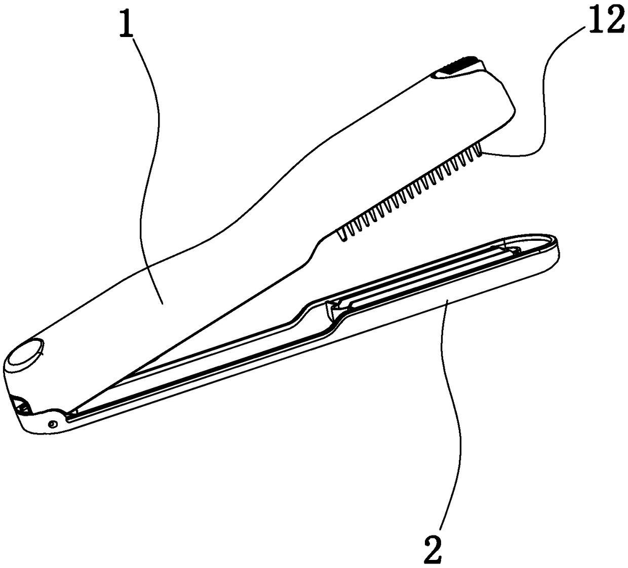
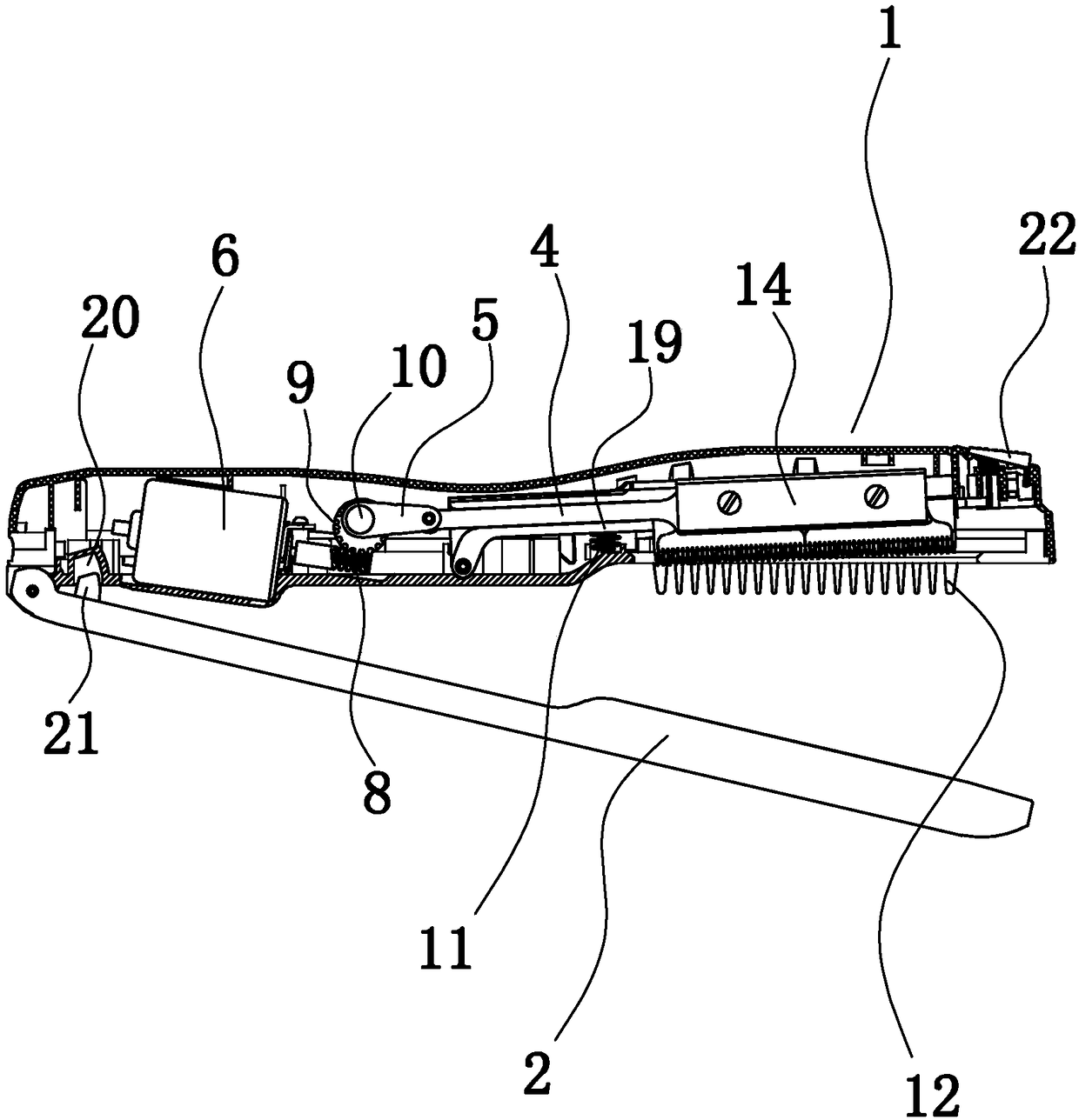
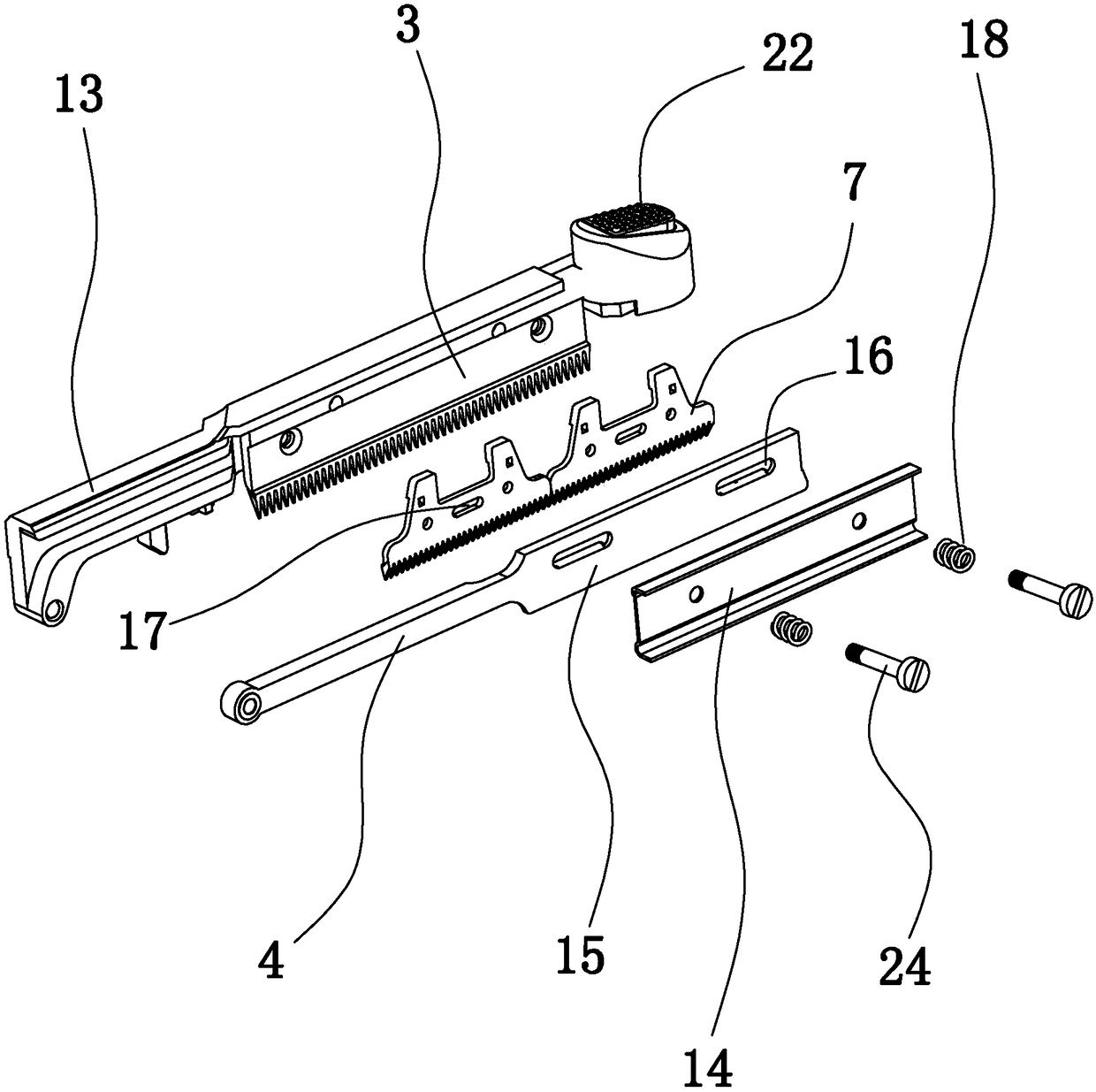
[0024] Embodiment 1: as Figure 1 to Figure 5 In the shown embodiment, an electric reciprocating cutting device includes a main casing 1 and a plywood bar 2 below the main casing. There is a return spring for pushing the plywood bar and the main shell apart. The main shell is equipped with a fixed blade 3, a pull rod 4, a transmission rod 5, a motor 6, and a movable blade that can move up and down relative to the fixed blade to make a cutting action. 7. The worm 8 connected to the output shaft of the motor, the worm wheel 9 matched with the worm, the eccentric shaft 10 arranged on the worm gear and the top spring 11 used to push the connecting rod upward. The shaft is rotationally connected with the worm wheel, the movable blade is connected with a pull rod, one end of the pull rod is hinged with one end of the transmission rod, and the other end of the transmission rod is connected with the eccentric shaft.

[0025] The main housing is provided with at least one comb 12, the...

Embodiment 2

[0028] Embodiment 2: the basic structure and implementation mode of this embodiment are the same as embodiment 1, and its difference is, as Figure 6 to Figure 7 As shown in , the main housing is provided with a push rod 25 slidably connected with the main housing and a crushing cylinder 26 fixed with the main housing. The slidable direction of the push rod is the up and down direction. Connecting rod 27, be provided with the crushing piston 28 that cooperates with the sliding seal of crushing cylinder in the crushing cylinder, the slidable direction of the crushing piston is the up and down direction, and the crushing piston is provided with a piston rod 29, the piston rod is arranged vertically and The piston rod is above the crushing piston, the lower end of the piston rod is connected to the crushing piston, the upper end of the piston rod is connected to the horizontal connecting rod, the upper end of the push rod is connected to the horizontal connecting rod, and the crus...


PUM


Abstract

The invention discloses an electric reciprocating type cutting device which comprises a main housing and a clamping plate strip positioned below the main housing; one end of the clamping plate strip is hinged to the main housing; a return spring for mutually jacking the clamping plate strip and the main housing is arranged between the clamping plate strip and the main housing; a fixed blade, a drawbar, a transmission rod, a motor, a movable blade, a worm connected with the output shaft of the motor, a worm gear matched with the worm, an eccentric shaft arranged on the worm gear, and a jacking spring used for upwards jacking a connecting rod are arranged in the main housing; the eccentric shaft is rotatably connected with the worm gear; the movable blade is connected with the drawbar; the drawbar is hinged to the transmission rod; and the transmission rod is connected with the eccentric shaft. The electric reciprocating type cutting device has the beneficial effects that: the structure is reasonable, hair can be effectively clamped, fixed and cut, stability in a using process is good, cut hair can be guaranteed to be orderly; and moreover, through electric cutting, cutting force is stable, and operation saves labor and is convenient.

Description

technical field [0001] The invention belongs to the technical field of hairdressing appliances, in particular to an electric reciprocating cutting device. Background technique [0002] At present, people's trimming of long hair (such as hair, etc.) is mainly done by manual shears (such as scissors). Cutting hair with manual shears is not only inefficient, but also poor in quality. Some people also use electric clippers to trim, However, the cutting range of the current electric clippers is small, and the trimming consistency is inconsistent. The effect control is completely dependent on the operator, and it is easy to have uneven hair length or uneven cutting surface after trimming. Contents of the invention [0003] In order to overcome the deficiencies in the prior art, the present invention provides a reasonable structure, which can effectively clamp, fix, and cut the hair, has good stability during use, and can ensure that the trimmed hair is neat. Electric reciprocat...

Claims


Application Information

Patent Timeline
Patent Type & Authority Patents(China)
IPC IPC(8): B26B19/02B26B19/06B26B19/42B26B19/38
CPCB26B19/02B26B19/06B26B19/3833B26B19/42
Inventor 牟丹
Owner 牟丹
Learn More