Head-mounted device

A head-mounted and projection device technology, applied in optical components, optics, instruments, etc., can solve problems such as manufacturing difficulties, reducing the rider's head protection ability, driving safety threats, etc., to save manufacturing costs and improve convenience And the effect of safety and good protection ability

Inactive Publication Date: 2017-04-19
CORETRONIC
View PDF4 Cites 2 Cited by
  • Summary
  • Abstract
  • Description
  • Claims
  • Application Information

AI Technical Summary

Problems solved by technology

[0003] At present, most of the helmets with display function use the windshield of the helmet to reflect the projection beam to the eyes of the rider. However, this design will cause the windshield to avoid aberrations in addition to reducing wind resistance, so there are Difficulties in manufacturing increase product cost, and the special shape design of the windshield based on reducing wind resistance will also be limited, which will affect the stability of riding at high speeds
In addition, some helmets with display function embed the projection system in the upper cover of the helmet, which will reduce the thickness of the buffer layer in the upper cover and reduce its ability to protect the rider's head.
In addition, some helmets with display function directly project the projection beam from the bottom up to the eyes of the rider, so that the rider must move his sight down to actually watch the information displayed by the projection beam. will still pose a great threat to driving safety

Method used


Image

  • Head-mounted device
  • Head-mounted device
  • Head-mounted device

Examples


Embodiment Construction

[0017] The foregoing and other technical contents, features and effects of the present invention will be clearly presented in the following detailed description of a preferred embodiment with reference to the accompanying drawings. The directional terms mentioned in the following embodiments, such as: up, down, left, right, front or back, etc., are only referring to the directions of the drawings. Accordingly, the directional terms are used to illustrate and not to limit the invention.

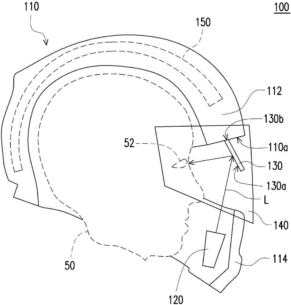
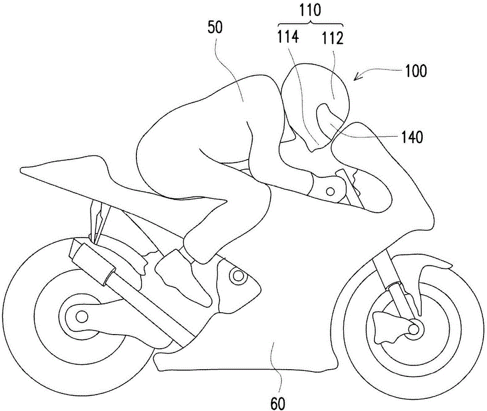
[0018] figure 1 is a schematic diagram of a head-mounted device according to an embodiment of the present invention. Please refer to figure 1 , the head-mounted device 100 of this embodiment includes a main body 110 , a projection device 120 , a light combining element 130 and a light-transmitting cover 140 . The main body 110 is, for example, a helmet used for riding a motorcycle or other helmets capable of protecting the head. figure 1 The main body 110 is illustrated by taking a safety ...


PUM


Abstract

The invention discloses a head-mounted device. The head-mounted device includes a main body, a projection device and a beam combiner is provided. The main body has an upper shade portion and a lower shade portion, wherein the upper shade portion and the lower shade portion have an opening defined therebetween. The projection device is disposed within the lower shade portion and adapted to generate a projection beam, and the projection beam is adapted to be transmitted from the lower shade portion to the opening. The beam combiner is connected to the upper shade portion and located in the opening, wherein the beam combiner is located at a transmission path of the projection beam to be adapted to reflect the projection beam into the main body. The head-mounted device can save the manufacturing cost and can improve convenience and safety for usage.

Description

technical field [0001] The present invention relates to a wearable device, and in particular to a head-mounted device with a display device. Background technique [0002] Head-mounted displays (HMDs) are wearable devices that use an optical projection system to project images or text information into the eyes of users. In addition to being used in the military field, head-mounted displays are also used in industrial production, simulation training, stereoscopic display, medical treatment, sports, video games and other fields. The rise of heavy motorcycle sports in recent years has driven the combination of head-mounted displays and traditional helmets. In detail, when the heavy locomotive is running at high speed, if the rider turns his sight away from the road ahead in order to watch the instrument panel, it will cause a high degree of danger on the ride. Based on the above, the safety helmet with a display function can instantly project the information on the dashboard t...

Claims


Application Information

Patent Timeline
Patent Type & Authority Applications(China)
IPC IPC(8): G02B27/01
CPCG02B27/0172G02B27/0176G02B27/017G02B2027/0159G02B2027/0198
Inventor 魏仲廷王祥骅
Owner CORETRONIC
Why Eureka
Try Eureka