Eureka AIR delivers breakthrough ideas for toughest innovation challenges, trusted by R&D personnel around the world.

Method for monitoring operation mode of direct-current system and operation states of disconnecting switches

A technology of operating status monitoring and isolating switches, which is applied in the field of electric power, can solve problems such as the inability to effectively identify the operation mode of the DC system, the inability to effectively monitor the status of the isolating switch, and the inability to give alarms for abnormal operating conditions, etc.

Active Publication Date: 2017-04-19
JIEYANG POWER SUPPLY BUREAU GUANGDONG POWER GRID CO LTD +2
View PDF3 Cites 10 Cited by
  • Summary
  • Abstract
  • Description
  • Claims
  • Application Information

AI Technical Summary

Problems solved by technology

[0011] The embodiment of the present invention provides a DC system operation mode and a method for monitoring the state of the isolating switch, which solves the problem that the state of the isolating switch in the current DC system cannot be effectively monitored, the operation mode of the DC system cannot be effectively identified, and the abnormal operation state cannot be given a warning band. Serious potential safety hazards and technical problems with low safety and reliability

Method used


Image

  • Method for monitoring operation mode of direct-current system and operation states of disconnecting switches
  • Method for monitoring operation mode of direct-current system and operation states of disconnecting switches
  • Method for monitoring operation mode of direct-current system and operation states of disconnecting switches

Examples


Embodiment Construction

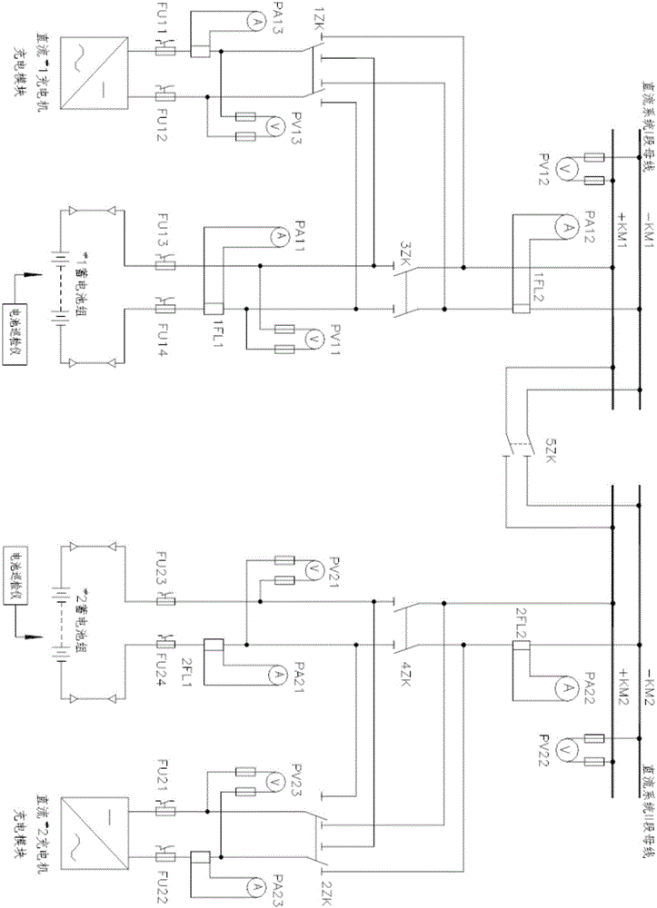
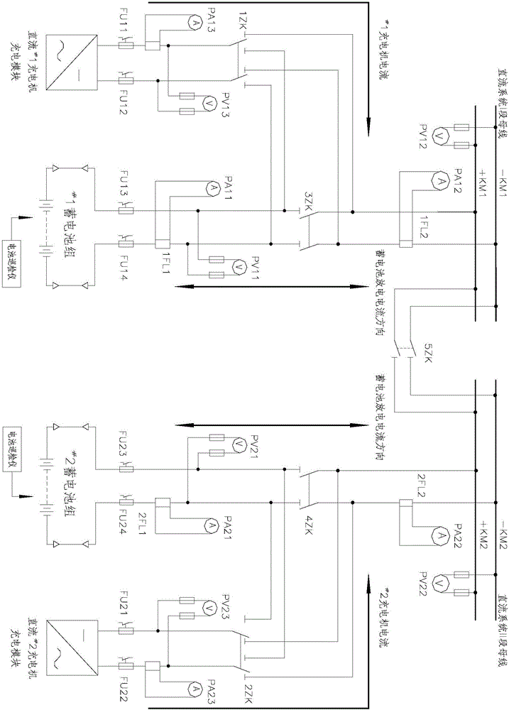
[0059] The embodiment of the present invention provides an operation mode of a DC system and a method for monitoring the state of an isolating switch, which solves the current technical problems of serious potential safety hazards and low safety reliability.

[0060] In order to make the purpose, features and advantages of the present invention more obvious and understandable, the technical solutions in the embodiments of the present invention will be clearly and completely described below in conjunction with the accompanying drawings in the embodiments of the present invention. Obviously, the following The described embodiments are only some, not all, embodiments of the present invention. Based on the embodiments of the present invention, all other embodiments obtained by persons of ordinary skill in the art without making creative efforts belong to the protection scope of the present invention.

[0061] see Figure 4 , an embodiment of a DC system provided in an embodiment ...


PUM


Abstract

The embodiment of the invention discloses a method for monitoring the operation mode of a direct-current system and the operation states of disconnecting switches. The disconnecting switch 5ZK, the first battery charger direct-current bus side disconnecting switch 1ZK, the second battery charger direct-current bus side disconnecting switch 2ZK, the first storage battery disconnecting switch 3ZK and the second storage battery disconnecting switch 4ZK are connected through a bus in the direct-current system, it is confirmed that turn-on and turn-off operation is accurate and is in place according to the voltage difference, current and position signals of the disconnecting switches in combination with a switch position auxiliary contact judgment method or a disconnecting switch loop current judgment method or a disconnecting switch two-side voltage difference judgment method or a combined analysis and judgment method, deblocking and blocking logic meets related operation processes, and potential fault hazards can be found. The technical problems that the states of disconnecting switches in an existing direct-current system cannot be effectively monitored, the operation mode of the direct-current system cannot be effectively recognized, an alarm cannot be given to an abnormal operation state, serious potential safety hazards are caused, and safety reliability is low are solved.

Description

technical field [0001] The invention relates to the field of electric power technology, in particular to a DC system operation mode and a method for monitoring the state of an isolating switch. Background technique [0002] At present, the DC power supply system used in power plants, substations and communication rooms of the power system is mainly composed of monitoring devices, chargers (including charger microcomputer control devices), battery packs, DC buses and their feeder units. Protection, control circuits, monitoring equipment, and communication equipment provide reliable working power, which plays a very important role in the safe and stable operation of power infrastructure. According to the relevant regulations of the power system on the DC power system, in order to verify the capacity of the battery pack, a checking discharge test should be carried out once every two years for the battery pack that has been in operation for less than 6 years, and for the battery...

Claims


Application Information

Patent Timeline
IPC IPC(8): H02J13/00H02J1/00
CPCH02J13/0006H02J1/00Y02B90/20Y02T10/70
Inventor 陈晓彬郑永强孙玉彤杨宗亮曹超陈庆鸿
Owner JIEYANG POWER SUPPLY BUREAU GUANGDONG POWER GRID CO LTD
Why Eureka
Eureka Blog
Learn More