Device and method for controlling on/off of current transformer

A start-stop control and converter technology, which is applied to output power conversion devices, electrical components, etc., can solve the problems of frequent start and stop, untimely operation by operators, and complicated on-site working conditions, and ensure safe start and stop. , easy to control, to meet the effect of frequent switch machine

Active Publication Date: 2017-04-19
ZHUZHOU CSR TIMES ELECTRIC CO LTD
View PDF8 Cites 2 Cited by
  • Summary
  • Abstract
  • Description
  • Claims
  • Application Information

AI Technical Summary

Problems solved by technology

In the actual field application of the converter device, due to the high power of the converter device and the complex working conditions on site (it may be frequently started and stopped), how to start and stop the operator safely is a very practical application problem
Existing schemes are as follows, but they all have certain defects: 1. Some control the start and stop of the entire device by giving the high and low level signals of the controller through the start / stop key or the knob switch; but only through the start / stop key or the The rotary switch controls the start and stop of the entire device by setting the high and low levels of the controller. There is a risk that the device may be damaged due to a system failure, and for applications that require frequent start and stop, the reliability of the start and stop key or the rotary switch is bound to be Affect system operation
2. Some are equipped with a display screen, the signal connection between the display screen and the controller, and the entire converter device is controlled through the display screen interface; but only through the display screen interface, there may be a problem that the operator cannot operate in time during emergency shutdown

Method used


Image

  • Device and method for controlling on/off of current transformer
  • Device and method for controlling on/off of current transformer
  • Device and method for controlling on/off of current transformer

Examples


Embodiment Construction

[0036] The present invention will be further described below in conjunction with the accompanying drawings and specific preferred embodiments, but the protection scope of the present invention is not limited thereby.

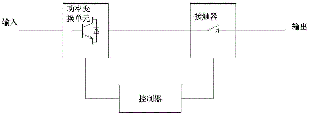
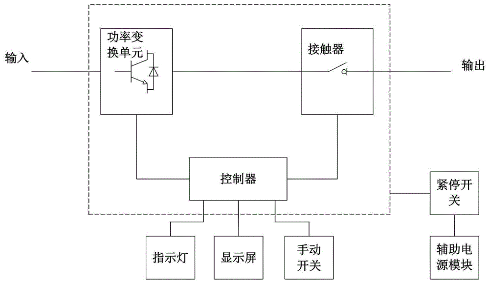
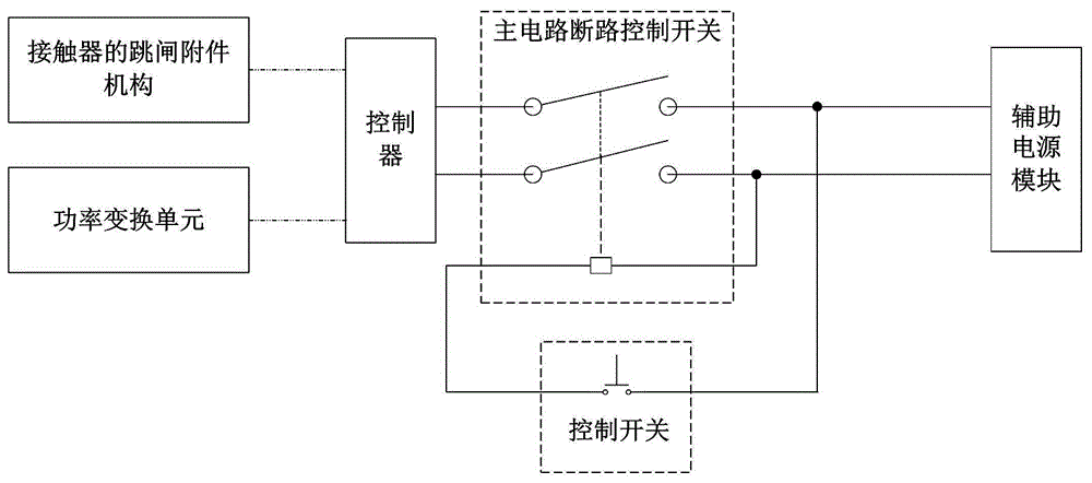
[0037] Such as figure 2 As shown, the converter start-stop control device in this embodiment includes a power conversion unit, a contactor, a controller and an auxiliary power supply module. After the electric energy is converted by the power conversion unit, it is output through the contactor. The controller is connected to the power conversion unit. To control its start or stop, the controller is connected with the contactor to control its opening or closing, the auxiliary power module is connected with the trip accessory mechanism of the controller and the contactor respectively, and the controller also includes a manual switch, a display screen and an indicator light ; The manual switch is used to provide a pre-start signal to the controller; the display sc...


PUM


Abstract

The invention discloses a device and method for controlling the on/off of a current transformer, and the device comprises a power conversion unit, a contactor, a controller, and an auxiliary power module. The electric energy is outputted through a contactor after being converted by the power conversion unit. The controller is connected with the power conversion unit, and is used for controlling the on/off of the power conversion unit. The controller is connected with the contactor, and is used for controlling the on/off of the contactor. The auxiliary power module is connected with the controller and a trip accessory mechanism of the contactor. The controller also comprises a manual switch, a display screen, and an indicating lamp. The manual switch is used for providing a pre-start signal for the controller. The display screen comprises a virtual key control, and is used for providing a start signal for the controller. The indicating lamp is used for displaying the working state of the current transformer. The device is convenient for control, can effectively guarantee the safe start and stop of the current transformer, and meets the frequency switching-on/switching-off operation demands.

Description

technical field [0001] The invention relates to the technical field of converter start-stop control, in particular to a converter start-stop control device and control method. Background technique [0002] The converter device is a device that controls the conversion circuit composed of semiconductor power switching devices to realize electric energy conversion through the controller. At the same time, in order to facilitate protection and control, the output of the converter device is equipped with a contactor control switch, etc. The schematic block diagram of the principle is as follows: figure 1 shown. The total output of the control system is controlled by the controller system to control the pull-in of the output contactor, and at the same time, a pulse control signal is sent to control the power output of the power conversion unit. In the actual field application of the converter device, due to the high power of the converter device and the complex working conditions...

Claims


Application Information

Patent Timeline
Patent Type & Authority Applications(China)
IPC IPC(8): H02M1/36
CPCH02M1/36
Inventor 唐洲管仁德张蓉陈艺峰蹇芳唐海燕王南张洪浩刘玉柱孙永进
Owner ZHUZHOU CSR TIMES ELECTRIC CO LTD
Why Eureka
Try Eureka