Office building lighting energy consumption splitting system and office building lighting energy consumption splitting method

A sub-system and energy consumption technology, applied in the field of lighting, can solve the problems of high energy consumption, energy saving and emission reduction, etc., and achieve the effect of convenient measurement, strong practicability, and simple structure

Inactive Publication Date: 2017-04-19
天津绿信节能科技有限公司
View PDF0 Cites 1 Cited by
  • Summary
  • Abstract
  • Description
  • Claims
  • Application Information

AI Technical Summary

Problems solved by technology

[0002] With the continuous advancement of science and technology and the rapid development of modern lighting technology, people's requirements for lighting technology are not only to meet the basic lighting, the current lighting system allows users to set different lighting scenes, such as choosing the preferred light color or dynamic lighting, especially It is the lighting of the building, which will change various color patterns at night. The scene of the building can be set by a professional lighting engineer or by the user. Several lighting scenes can be combined into a lighting scheme, just like a playlist. As more and more new lighting systems, the lighting functions provided will also increase, and the energy consumption of lighting will increase accordingly. With more and more lighting functions, the lighting energy Energy consumption is usually calculated uniformly, and users cannot know in time which part of the lighting system consumes more energy. With the increasing shortage of energy, energy conservation and emission reduction are imperative. The discharge has caused a lot of trouble. In order to make energy saving and emission reduction go smoothly, it is imperative to split the energy consumption of building lighting.

Method used


Image

  • Office building lighting energy consumption splitting system and office building lighting energy consumption splitting method

Examples


Embodiment Construction

[0022] It should be noted that, in the case of no conflict, the embodiments of the present invention and the features in the embodiments can be combined with each other.

[0023] The present invention will be described in detail below with reference to the accompanying drawings and examples.

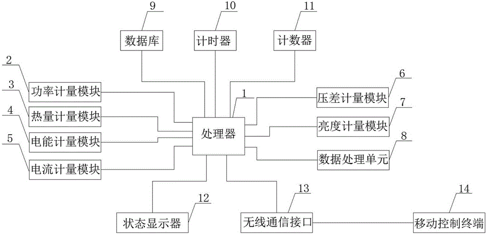
[0024] Such as figure 1 As shown, an office building lighting energy consumption splitting system is characterized in that it includes a processor 1, a mobile control terminal 14, and a power metering module 2 connected to the processor 1, a heat metering module 3, and an electric energy metering module 4 , current metering module 5, differential pressure metering module 6, brightness metering module 7, data processing unit 8, database 9, timer 10, counter 11, status display 12, wireless communication interface 13, described processor 1 is single-chip microcomputer, all The database 9 is a SQL-Server database, the wireless communication interface 13 is a WiFi interface, the mobile contr...


PUM


Abstract

The invention provides an office building lighting energy consumption splitting system and an office building lighting energy consumption splitting method. the office building lighting energy consumption splitting system comprises a processor, a mobile control terminal, and a power measurement module, a heat metering module, a power measurement module, a current measurement module, a voltage difference measurement module, a brightness measurement module, a data processing module, a database, a timer, a counter, a status display, and a wireless communication interface connected with the processor, wherein the mobile control terminal and the processor perform data transmission through the wireless communication interface. According to the office building lighting energy consumption splitting system and the office building lighting energy consumption splitting method of the invention, through arranging multiple acquisition modules, various energy consumption amounts of the lighting device can be acquired more comprehensively, various power consumption of the lighting device can be obtained more intuitively through processing on various precise data, the values of various power consumption can be transmitted to the remote terminal, measurement and use are more convenient, the structure is simple, the use is convenient, and the practicability is strong.

Description

technical field [0001] The invention belongs to the technical field of lighting, and in particular relates to a system and method for splitting energy consumption of office building lighting. Background technique [0002] With the continuous advancement of science and technology and the rapid development of modern lighting technology, people's requirements for lighting technology are not only to meet the basic lighting, the current lighting system allows users to set different lighting scenes, such as choosing the preferred light color or dynamic lighting, especially It is the lighting of the building, which will change various color patterns at night. The scene of the building can be set by a professional lighting engineer or by the user. Several lighting scenes can be combined into a lighting scheme, just like a playlist. As more and more new lighting systems, the lighting functions provided will also increase, and the energy consumption of lighting will increase according...

Claims


Application Information

Patent Timeline
Patent Type & Authority Applications(China)
IPC IPC(8): H05B37/02
CPCH05B47/10
Inventor 刘魁星
Owner 天津绿信节能科技有限公司
Why Eureka
Try Eureka